IP Tunnels
Introduction
About this Document
In this document, we explain how the concept and configuration of IP tunnels (encapsulation devices) on the AXS GUARD appliance. This document was last updated on 21 Jun 2019.
Tunnel Types
An IP tunnel is an Internet Protocol (IP) network communications channel between two networks. It is used to transport another network protocol by encapsulation of its packets. IP tunnels are often used for connecting two disjoint IP networks that don’t have a native routing path to each other, via an underlying routable protocol across an intermediate transport network.
IP-in-IP Tunnels
Sometimes called ipencap, is IP encapsulation within IP and is described in RFC 2003

Unlike GRE tunnels, IP-in-IP tunnels cannot carry multicast traffic, other protocols or IPv6 packets between networks. IP-in-IP tunnels have the following advantages:
-
Lower overhead due to less encapsulated layers.
-
Use of IP packets for encapsulation can allow for support (e.g. forwarding) on devices which don’t support the GRE protocol.
-
Supports a single tunnel between two endpoints.
GRE-in-IP Tunnels
GRE is a tunneling protocol that was originally developed by Cisco and can be used to transport multicast traffic through a GRE tunnel. GRE (defined in RFC 2784 and updated by RFC 2890) goes a step further than IP in IP, adding an additional header of its own between the inside and outside IP headers.

A GRE tunnel creates a point-to-point private connection like a virtual private network (VPN) and has the following advantages:
-
GRE tunnels wrap multiple protocols on a single backbone protocol.
-
They provide a solution for networks with limited hops.
-
They can connect discontinuous subnets.
-
They provide better support for devices and systems that miss-interoperate IP-in-IP packets or are unable to forward them.
Summary
-
GRE can theoretically encapsulate any layer three protocol with a valid Ether type, unlike IP in IP, which can only encapsulate IP packets.
-
Both tunnel types should only be used in trusted networks, as they offer no encryption. You should used IPsec, OpenVPN, SSTP, PPTP or L2TP to tunnel traffic over insecure networks, such as the Internet.
-
IP tunnels are bi-directional and must be configured on each endpoint, e.g. A to B and B to A.
-
Appropriate routing must be added on each endpoint.
Configuration and Parameters
Example with Internet Failover
Assume you have two remote sites (A & B) that are physically connected with a leased line. Each site has one Internet connection.
Let’s imagine that site A loses it’s Internet connection because there is a technical issue with the ISP. With an IP tunnel, site A can use the Internet connection of site B seamlessly while its own connection is down.
Note that the Internet Redundancy feature must be enabled for this setup.

-
Make sure to configure the Tunnel Interface type as Internet.
-
The Internet can be reached via the default gateway of Site B, e.g. 192.168.240.1/24. This range must be routed over the IP Tunnel (Network > Internet Redundancy).
Tunnel Configuration
-
Navigate to Network > Devices > Enc.
-
Click on Add new.
-
Enter the settings as explained in the tables below.
-
Update your configuration when finished.
-
Add the appropriate routing entries.
-
Reboot your system.
-
Configure the IP tunnel on the other endpoint.
| Parameter | Description |
|---|---|
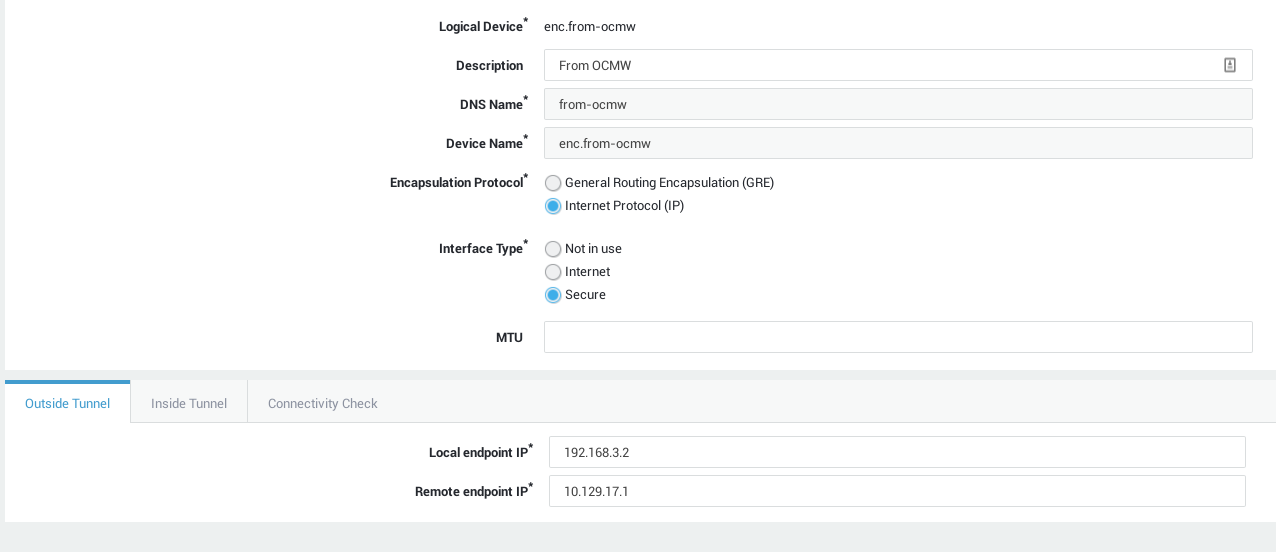
DNS Name |
The name as known by the internal DNS server. |
Device Name |
The name to be given to the tunnel device, e.g. iptun1. The resulting name will be enc.iptun1. |
Encapsulation Protocol |
Select the encapsulation type (GRE or IP). |
Interface Type |
Not in use: Select to disable an active IP tunnel device. Internet: An "internet" tunnel device will not be connected directly to the Internet, but it can route its Internet traffic via the remote tunnel endpoint. Secure: Traffic entering via the tunnel device will be able to pass through the AXS Guard appliance. |
MTU |
The Maximum Transmittable Unit (MTU) is the maximum size of data transmissions on the physical layer. The standard set by IEEE802.3 specifies the MTU of Ethernet is 1500 bytes, which is also the factory default configuration. |
| Parameter | Description |
|---|---|
Local enpoint IP |
Enter the IP address of the local encapsulation device, i.e. the device that will be routing IP or GRE packets . |
Remote endpoint IP |
Enter the IP address of the remote encapsulation device (destination). |
| Parameter | Description |
|---|---|
Local virtual enpoint IP |
Enter the IP address of your local IP tunnel device . |
Remote virtual endpoint IP |
Enter the IP address of the remote IP tunnel device (destination). |
| Parameter | Description |
|---|---|
Connectivity Check? |
Select this option to specify IP addresses for connectivity checks. The appliance periodically will send ICMP (ping) messages to the specified IP address(es) to check connectivity. System administrator(s) will be notified by e-mail if a network device fails. If unchecked, the appliance will send ICMP messages to the Internet root servers. Connectivity checks cannot be disabled, but timeout values can be configured under Network ▸ Monitoring. Never use master or slave IP addresses for network connectivity checks. |
Connectivity check IPs |
Enter the IP address(es) to be used by the connectivity check. |
Firewall Configuration
To allow easy logging, it is recommended to use advanced firewall rules on both tunnel endpoints (A & B), for example:
-N _FAILOVER
-F _FAILOVER
-A _FAILOVER -m limit --limit 5/m --limit-burst 7 -j LOG --log-level 7 --log-prefix "firewall: Failover: "
-A _FAILOVER -j ACCEPT
-A _AFR_FWD -i enc.lan.A -j _FAILOVER
-A _AFR_FWD -i enc.lan.A -o enc.int.A -j REJECT