Bandwidth Management
Introduction
About this Document
This AXS Guard guide serves as a reference source for technical personnel, system administrators and network administrators. It explains the concepts and the operation of the AXS Guard bandwidth management module.
Examples used in this Guide
All setups and configuration examples in this guide are executed as an advanced administrator. Some options are not available if you log in as a full administrator or a user with lower access privileges.
As software development and documentation are ongoing processes, the screenshots shown in this guide may slightly deviate from the current user interface.
General Concepts
Overview
In this chapter, we explain the general concepts and purpose of bandwidth management. Topics covered in this chapter include:
-
A definition of bandwidth management and when to use it.
-
Bandwidth management vs. Internet Redundancy.
-
AXS Guard Bandwidth Control, TCP flow and congestion control.
What is Bandwidth Management?
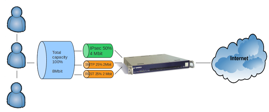
Bandwidth management is the process of measuring and controlling communications (traffic, packets) on a network link, to avoid filling the link to its full capacity or even overfilling the link, which would result in network congestion and poor performance. Note that bandwidth management does not allow you to increase your existing Internet bandwidth capacity; only your Internet Service Provider can adjust your Internet bandwidth.
Bandwidth management is essentially used in large networks to optimize critical traffic to Internet servers and servers in your corporate network segments. It avoids possible congestion and ensures the continuity of critical services, such as IPsec (VPN) tunnels and VoIP communications during network traffic peaks.
Bandwidth Management vs. Internet Redundancy
The Internet Redundancy Module has been designed for and only applies to AXS Guard appliances with two or more Internet devices. It allows administrators to route specific traffic via a specific Internet device, e.g. you can route all VoIP traffic via the first Internet device and route all audio streaming traffic via the second Internet device. For more information, see the Internet Redundancy How To, which is accessible via the Documentation button in the AXS Guard Administration Tool.
The Internet Redundancy Module does not allow you to regulate the traffic flow routed via a specific device, e.g. to control and regulate the bandwidth which should be made available for VoIP traffic. This can only be achieved through Bandwidth Management, which allows administrators to regulate outgoing network (upstream) traffic based on ports, protocols, IP addresses and other network protocol properties.
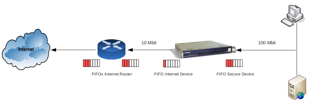
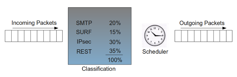
The FIFO Principle
Hosts in a network do not all operate at the same speed. Your LAN and DMZ operate at a faster speed than your WAN. When a host sends data across the network at a faster speed than allowed by the receiving host, a data overrun occurs. Therefore, FIFO (First In, First Out) and other control mechanisms are used to prevent loss of data or connection failures.
In a network, many FIFO buffers are in control (as illustrated below). As mentioned in the previous paragraph, FIFO is an acronym for First In First Out. This expression describes the principle of a queue processing technique or servicing conflicting demands by ordering processes by first-come, first-served behavior; what comes in first is handled first, what comes in next waits until the first request is completed, etc. In the following sections, we explain some important features of bandwidth management.
Countering Network Saturation
The AXS Guard Bandwidth Management module allows you to regulate any outgoing traffic on any of its network devices, e.g. traffic originating from your secure LAN and DMZ towards the Internet, traffic originating from one secure LAN device to another LAN device, etc. IPsec devices are considered a part of the secure network and require special consideration. Responses to incoming requests are a part of outgoing traffic and can be regulated as well.
Bandwidth Management prevents data loss and ensures the continuity of critical services, such as VoIP and IPsec. It does this by controlling the FIFO buffers of its network devices. However, it is important to note that the Bandwidth Management module only regulates network traffic when this is necessary, i.e. when your network is reaching its bandwidth limit (point of saturation) or has to handle lots of simultaneous classified requests and needs to prioritize critical traffic. During normal network traffic conditions, bandwidth is assigned automatically and dynamically by AXS Guard. Bandwidth which isn’t used can be recovered by other queues and can be prioritized to maximize efficiency.
Data Flow Regulation Methods
The Bandwidth Management module uses certain methods to regulate the data flow and to prevent network traffic congestion. The AXS Guard regulates the data flow by:
-
Limiting the upload speed towards the AXS Guard, which is slightly less than the available speed. As a result, the FIFO buffers on the ISP side get depleted.
-
Slowing down the connections that are coming in too fast. This is achieved by delaying network packets of communication protocols according to the leaky bucket principle, which is explained further.
-
Prioritizing network traffic according to its importance within your organization.
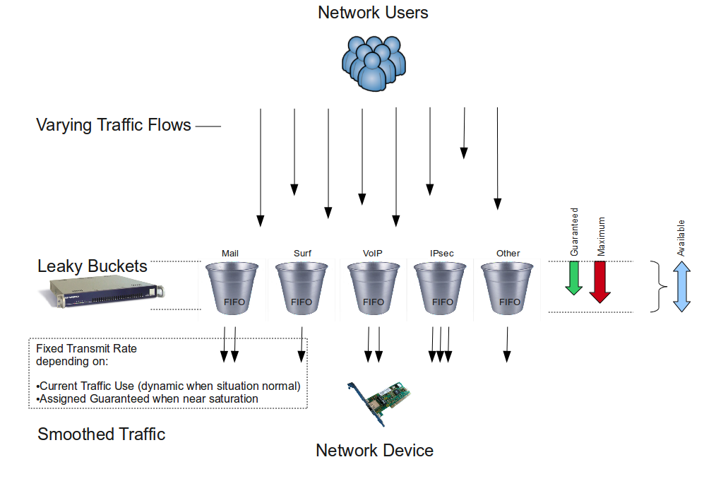
The leaky bucket algorithm is used to control the rate at which traffic is sent to a network. It provides a mechanism by which traffic bursts originating from a given network can be shaped to a steady stream of traffic towards another network. Classes (explained in Traffic Classes) define each traffic stream to be shaped.
Info
Most modern applications are equipped with their own congestion control mechanisms.
Protocols and Devices
The AXS Guard Bandwidth Management module allows you to manage outgoing (upstream) network traffic for any of its network devices, including VLAN and VPN devices, such as IPsec devices. Administrators can regulate the data flow on a protocol basis. The protocols are listed in the table below.
| Supported Protocols | Description |
|---|---|
TCP |
Transmission Control Protocol. This is a transport layer protocol that establishes a reliable, full duplex, data delivery service used by many TCP/IP application programs, i.e. the TCP protocol provides acknowledgement of received packets. The TCP software uses the IP protocol to transmit information across the Internet. |
UDP |
User Datagram Protocol. One of the protocols for data transfer that is comparable to the TCP/IP suite of protocols. UDP is a "connectionless" protocol in that UDP makes no provision for acknowledgement of received packets. |
ICMP |
ICMP is a Network layer protocol that carries control messages, such as error or confirmation messages. This is the protocol that is used by the ping command. |
GRE |
Generic Routing Encapsulation (GRE) is a tunneling protocol developed by Cisco Systems that can encapsulate a wide variety of network layer protocol packet types inside IP tunnels, creating a virtual point-to-point link to routers at remote points over an Internet Protocol (IP) internetwork. GRE has IP protocol number 47. For more information about GRE, consult the AXS Guard IPsec How To, which is accessible via the Documentation button in the Administrator Tool. |
ESP |
The Encapsulating Security Payload (ESP) is a protocol used by the IPsec framework. It provides integrity, authentication and encryption to IP packets. ESP has IP protocol number 50. For more information about ESP, consult the AXS Guard IPsec How To, which is accessible via the Documentation button in the Administrator Tool. |
Info
- You can also specify other properties in the filters such as destination ports, IP addresses, etc. for protocols which are not listed in the table above.
- IPsec has special requirements (see Managing Bandwidth of an IPsec Device)
Level of Operation
There are four security levels on the AXS Guard; the user, the group, the computer and the system level. The AXS Guard Bandwidth Management module operates at the system level. You cannot assign Bandwidth Schemes to individual users or groups. However, you can specify IP ranges or individual IP addresses to which Bandwidth Schemes must be applied (This is done with filters.
For detailed information about the AXS Guard security levels, see the AXS Guard System Administration How To, which is accessible via the Documentation button in the Administrator Tool.
Summary
The AXS Guard Bandwidth Management module allows you to regulate the outgoing traffic stream (upstream traffic) of all its network devices, e.g. traffic originating from your secure LAN and / or DMZ devices which is leaving via your Internet device or traffic that is traveling from one secure LAN to another. By doing so, you can prevent data loss and ensure the continuity of critical services, such as VoiP, IPsec tunnels or e-mail. This is especially important in networks with a large user base, where lots of network traffic towards the Internet or other networks is likely to be generated and, as a result, network link FIFO buffers become quickly overflowed. It is important to note that the Bandwidth Management module does not allow you to increase your bandwidth capacity, i.e. to specify a bandwidth superior to the real capacity of the network hardware. To increase the bandwidth of your Internet connection, you must contact your Internet Service Provider.
Since the bandwidth of LAN and DMZ devices is always superior to the bandwidth of your Internet device(s), the AXS Guard Bandwidth Management module allows you to limit the upload speed, based on the type of traffic, from your secure LAN or DMZ towards the AXS Guard. In case network saturation occurs, the AXS Guard Bandwidth Management module slows down existing connections, by delaying packets of these connections, in accordance with the amounts guaranteed per traffic type. It is possible to delay and control all types of IP traffic, such as UDP, ESP, GRE and ICMP traffic.
The AXS Guard Bandwidth Management module only acts when necessary. This means that under normal traffic conditions, the available bandwidth is divided dynamically. When saturation is about to occur or is occurring, traffic is regulated and prioritized in accordance with the configured percentages per traffic type.
Traffic Classification
Overview
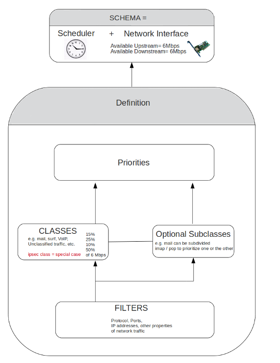
In this chapter, we explain how the AXS Guard uses Classes of traffic to manage bandwidth. Classes must be defined by system administrators. Each Class consists of Filters, which define the protocols, ports, IP addresses and other properties of packets to be regulated. Finally, the Classes are added to a Schema, which determines when Bandwidth Management is active for the created classes.
Topics covered in this chapter include:
-
Available, Guaranteed and Maximum Bandwidth.
-
Prioritizing traffic: Traffic with a higher priority is automatically assigned any remaining (free) bandwidth over traffic with a lower priority level.
-
Classes and Subclasses: classes define the guaranteed and maximum bandwidth to be made available for a certain type of traffic. Classes can also be divided into subclasses, which allow you to prioritize and manage traffic within a given Class.
-
Filters: Filters define the type of traffic on which the Bandwidth Management module should act, i.e. source and destination IP addresses, port numbers, protocols, etc. Classes are useless without filters; i.e. Filters are the backbone of Classes. They are the smallest component of the Bandwidth Management module.
-
Unclassified traffic, i.e. traffic for which no specific Class / Filter has been created.
-
Bandwidth Schemas, which determine when a Class is active and which network device is monitored.
-
Bandwidth Definitions, which are a collection of Classes.
Available, Guaranteed and Maximum Bandwidth
Overview
Each network device has a hard limit which cannot be exceeded (the maximum available bandwidth of a network device, supported by the hardware).
You can specify a guaranteed and a maximum percentage of bandwidth to be made available per traffic Class. Both percentages represent a portion of the total available bandwidth of a network device. In the following sections, we introduce the concepts of available, guaranteed and maximum bandwidth.
Available Bandwidth
The available bandwidth of a network device is the maximum capacity of data it can send / receive during a specific time frame. This capacity is most commonly expressed in kilobits per second (Kbits/s) or megabits per second (Mbits/s). 1 kilobit is equivalent to 103 bits, 1 megabit is equivalent to 10 6 bits.
Each network device has a maximum available upstream (upload) and a maximum available downstream (download) in accordance with its hardware specifications. You cannot manage the bandwidth of a network device, unless you specify the available bandwidth on that network device.
Guaranteed Bandwidth
In networking or telecommunications, the guaranteed bandwidth is the capability for transmitting continuously and reliably at a specified transmission speed (rate) via a certain network device. The guarantee makes it possible to reliably send time-dependent data (such as VoIP, video or multimedia) over the line.
The guaranteed bandwidth consists of a defined portion of the total available bandwidth of a network device; it cannot exceed the maximum bandwidth of a network device.
In short, the guaranteed bandwidth determines how much bandwidth of the total available bandwidth should be reserved when needed by a specific type of traffic. Bandwidth which isn’t needed or used is automatically recovered by other queues (classes of traffic) to maximize efficiency. One of the principles behind guaranteed bandwidth is the leaky bucket algorithm.
Important
The sum of the guaranteed bandwidth per Class can never exceed 100% of the total available bandwidth.
Maximum Bandwidth
The maximum bandwidth is a maximum percentage of the total available bandwidth. This maximum or a portion thereof can only be used if that bandwidth is available. In other words, the guaranteed bandwidth may be exceeded up to the specified maximum percentage, on the condition that this does not interfere with other traffic. The maximum percentage specified for a Class can never exceed 100% of the available bandwidth.
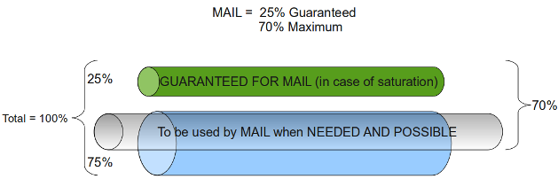
Example: SMTP Traffic
Suppose you specify a guaranteed bandwidth of 25% and a maximum bandwidth of 70% for SMTP traffic. The result is that SMTP always has 25% of the total available bandwidth at its disposal and that this can be extended up to 70%, if needed by SMTP and as long as this does not interfere with other traffic (as illustrated below).
Important
The sum of the maximum bandwidth per Class can exceed 100% of the total available bandwidth, since the maximum or a portion thereof is only used if network conditions allow it and if required.
Prioritizing Traffic
The AXS Guard Bandwidth Management module uses a guaranteed system for each defined traffic type or Classes, which are explained further in Traffic Classes. This means that a specific percentage of the total available bandwidth of a network device is certain to be assigned to a Class when saturation occurs.
The remaining bandwidth percentage can be allocated to any class whenever required. 3 mechanisms currently exist to divide this remaining bandwidth:
-
Class prioritizing: A Class or Subclass is assigned the remaining bandwidth according to its priority settings, i.e. the importance given to that traffic in your network. You only can assign priorities to the lowest leaf, i.e. if a Class is divided into Subclasses, you can only set priorities for the Subclasses.
-
Maximum bandwidth: Is the maximum bandwidth to be assigned to a given Class. The priority does not affect the amount of allocated bandwidth. The specified maximum is only assigned when network conditions allow it.
-
Round robin: Classes with the same priority and for which bandwidth remains available, alternately are assigned the remaining bandwidth by the AXS Guard.
Important
- Prioritizing means allocating more available bandwidth for a connection whenever remaining bandwidth is available. This means that the delay for that connection drops; however it also means that other traffic with a lower priority can be starved, have longer delays or be terminated.
- Only prioritize Classes which really need low delays; example video, audio and VoIP traffic.
Traffic Classes
A class is a logical container that defines traffic with common attributes. In turn, a class is composed of smaller containers, called filters and can be assigned a priority. Each class requires a guaranteed and a maximum bandwidth percentage. The purpose of classes is to help you keep a clear overview of divided bandwidth.
Example: Updates Class
You can create an updates class for Microsoft Windows updates, where you guarantee 25% of the total bandwidth and assign a maximum bandwidth use of 90%.
You can create a surf class for Internet browsing, where you guarantee 15% of the total bandwidth and assign a maximum bandwidth use of 75%.
There are 2 types of Classes:
-
The system default small class.
-
User-defined classes, which have to be created and maintained by system administrators.
The Default Small Class
The bandwidth of the upstream traffic is affected by the incoming traffic (e.g. for each incoming TCP SYN packet an SYN/ACK packet needs to be sent out). To minimize this effect, a default small Class exists. This Class reserves bandwidth for these small reply packets and is automatically added when a new Definition is created.
Recommendations
When you create Classes or Subclasses, it is recommended to give a higher priority to protocols which send out small packets and consequently have small delays. This way protocols which are less sensitive to delays, such as SMTP don’t get priority over protocols which are very sensitive to delays, such as audio and video streaming protocols, VoIP, etc.
Traffic Subclasses
Classes can be divided into Subclasses.
A Subclass is a user-defined, logical unit of traffic sharing within a Class. Similarly to Classes, it is a label to which a guaranteed and a maximum bandwidth percentage have to be assigned. You can assign a priority to each Subclass. Pay special attention when entering a Subclass' guaranteed bandwidth values, as noted further.
Subclasses allow you to prioritize traffic within a same Class (by assigning more bandwidth to the most important Subclass and setting priority levels. You cannot assign priorities to a Class containing Subclasses, i.e. the parent Class.
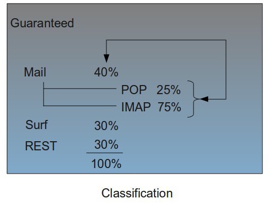
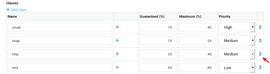
You can create a class mail for which you guarantee 40% of the total available bandwidth and to which you assign a maximum bandwidth use of 80%.
Example: Subclasses
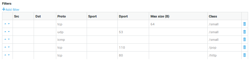
The mail class can be further subdivided, e.g. per protocol. Hence, you can create a Subclass pop and another Subclass imap. In this example, we assume that imap is the most important Subclass (needs more bandwidth than pop).
The guaranteed bandwidth for pop could be 25%, which is 25% of the guaranteed bandwidth of the mail class, in other words 25% of 40% = 10% of the total available bandwidth. The maximum bandwidth could be set to 60%.
The guaranteed bandwidth for imap could be 75%, which is 75% of the guaranteed bandwidth of the mail Class, in other words 75% of 40% = 30% of the total available bandwidth. The maximum bandwidth could be 80%.
Info
The maximum bandwidth of a Subclass can never exceed 100% of the total bandwidth, but can be determined freely, since this margin is only used if available and as long as it does not interfere with other traffic or active bandwidth schemes.
Traffic Filters
While classes and subclasses are logical containers to help you keep things organized, filters define the type of traffic to be matched by these classes and subclasses. Filters are therefore required elements; Each class or subclass must contain at least one filter to be functional.
Filters must contain at least one of the following elements:
| Parameter | Description |
|---|---|
TOS |
Select the appropriate value to be matched by the filter. The TOS byte in the IP header indicates the purpose of the datagram, e.g. delay, precedence, reliability, minimum cost, throughput etc. |
Proto |
Select the protocol to match. With TCP, you can decide whether or not to match TCP flags. (Also see notes below). If no flag is selected, the filter will match all TCP packets. In case one or more flags are selected, the filter will only match the packets with the specific flags set or unset (according to the selected option). |
Source Address |
The source IP address or network range to be matched by the filter. This is a single IP address or IP address range in your secure LAN or DMZ. Use the CIDR notation when specifying a range, e.g. |
Destination Address |
The destination IP address or IP range to be matched by the filter. This is an address or address range of an external network. Use the CIDR notation to specify a range, e.g. |
Max size |
The maximum size (expressed in bytes) of packets to be matched (optional). If the size of a matching packet exceeds this value, the packet will be discarded. Only packets of an equal or inferior size will be matched. |
Source Port |
The source port(s) to be matched by the filter. You can specify multiple ports in a comma-separated list, e.g. 2000, 2001, 2002 |
Destination Port |
The destination port(s) to be matched by the filter. You can specify multiple ports in a comma-separated list, e.g. 80, 81, 82 |
AXS Guard has a standard queuing mechanism for each network device, named pfifo_fast. Although this mechanism uses the first in first out principle (FIFO), it has 3 separate internal classes of its own, where the class with the lowest value (possible values are 0, 1 and 2) has the highest priority.
Within each of these separate classes (0, 1 and 2) the FIFO principle is applied. The AXS Guard uses these classes so that IP packets which contain matching TOS values are properly queued.
Priorities
-
Class 0 is used for interactive traffic. Interactive traffic will be sent before any other traffic.
-
Traffic that has no TOS set (meaning the TOS is 0) will be sent before all non-interactive traffic.
-
Non-interactive traffic that is marked as "Reliable" or "High Throughput" is sent after everything else. (In particular this means requesting "High Throughput" will cause the packet to be sent at the lowest priority.)
-
Setting the Cheap bit in the TOS will cause the packet to be sent at the lowest priority, even if it’s interactive.
| Value | pfifo_fast class | Binary representation | Decimal representation |
|---|---|---|---|
Minimize delay (md) |
0 (interactive) |
1000 |
8 |
Maximize throughput (mt) |
2 (bulk) |
0100 |
4 |
Maximize reliability (mr) |
1 (best effort) |
0010 |
2 |
Minimize monetary cost (mmc). Uses the "cheapest" link. Speed and volume are irrelevant. |
2 (filler) |
0001 |
1 |
Normal Service (No TOS value) |
1 (best effort) |
0000 |
0 |
Recommendations
-
Assign your Minimum Delay traffic to a High priority class.
-
Assign your regular traffic to a Medium priority class.
-
Assing your Maximize reliability traffic to a class with sufficient bandwidth and a High priority.
-
Assign your Minimize monetary costs traffic to the rest class.
-
Assign your Maximize throughput traffic to the rest class or another, custom class that can guarantee a specific traffic volume.
Info
The flag bits of the TCP protocol are outside the scope of this manual. For detailed information about the TCP protocol and the 6 flag bits (URG, ACK, PSH, RST, SYN and FIN), see the appropriate online references and RFCs.
Unclassified Traffic
Traffic for which no specific classes have been or can be defined, in other words unclassified traffic, can be added to a rest Class. This allows the Bandwidth Management module to optimize and prioritize traffic not only for the existing traffic Classes, but also for other, unclassified traffic, which is more than likely to be generated in your network.
Example: Unclassified traffic
Assume that you defined a Class for IPsec traffic for which 35% of the available bandwidth is guaranteed and to which a maximum of 80% has been assigned.
Assume that you have defined a Class for HTTP traffic for which 15 % of the available bandwidth is guaranteed and to which a maximum of 70% has been assigned.
Assume that you have defined a Class for E-mail traffic for which 30% of the available bandwidth is guaranteed and to which a maximum of 70% has been assigned.
The remaining bandwidth that can be guaranteed is 20% of the total available bandwidth. You can create a rest Class and guarantee 20% for that rest Class. The maximum for the rest Class can be set to 50%. This guarantees 20% of the total bandwidth for other types of traffic, e.g. FTP traffic, SSH traffic, etc. It also allows these others types of traffic to use 50% of the total bandwidth if it is available.
Traffic Definitions
A traffic definition is a collection of classes. Traffic definitions must be assigned to a schema in order for classes to be functional.
| Parameter | Description |
|---|---|
Name |
A label for the definition (required), e.g. dsl-internet. |
Description |
An optional description for the definition, e.g. Primary Internet Connection. |
Classes / Subclasses / Priorities / Filters |
The classes, subclasses and filters to be included in the definition. |
Schemas
A bandwidth schema determines when a given traffic definition is enforced.
Schemas allow you to:
-
Assign the maximum bandwidth as soon as it becomes available, e.g. after office hours users can benefit from the total available bandwidth to browse the Internet, while during office hours the maximum bandwidth for this purpose can be limited to 40% of the total bandwidth.
-
Recycle existing definitions, e.g. you can simply disable a definition; you do not need to delete it.
-
Disable Bandwidth Management during specific periods.
| Options and Parameters | Description |
|---|---|
Description |
A description for the schema, e.g. sdsl-line. This is a required field. |
Enabled |
Check to enable the schema. Uncheck to disable the schema. |
Days |
If no days are selected and the schema is enabled, the selected traffic definition will be activated until the first day for which a schema is configured. |
Time |
The start time of the selected traffic definition. Use the following time format: |
Device |
The network device which handles the network traffic as defined in the classes making up the definition. |
Definition |
The traffic definition to be used for this schema. |
Info
To disable bandwidth management during the period specified in a schema, use the Disable qos definition.
Summary
In this chapter, we explained how traffic can be categorized by means of Classes. Classes allow you to create traffic categories, e.g. mail, for which you guarantee a certain percentage of the total available bandwidth and to which priorities can be assigned. The maximum bandwidth value allows a given Class to use more than the guaranteed bandwidth, provided that this bandwidth is available. The total percentage of guaranteed bandwidth can never exceed 100% of the total available bandwidth of a network device. Similarly, the maximum bandwidth per Class can never exceed 100% of the total available bandwidth.
Classes can optionally be further divided into Subclasses, which allow you to prioritize traffic within a same Class by guaranteeing the most bandwidth to the most important Subclass and by setting priorities.
Classes and Subclasses must contain at least one Filter. Filters define the type of traffic to be regulated and allow you to specify traffic properties such as protocols, ports, IP addresses and other protocol-specific items . For IPsec, a special Class needs to be created. The defined maximum bandwidth in the ipsec Class is automatically applied to all IPsec devices and depending E-tunnels.
It is recommended to create a separate Class for undefined or unclassified traffic, i.e. a rest Class. This allows you to guarantee the remaining bandwidth for traffic which is likely to be generated, but which isn’t qualified (labeled).
Once your Classes are fully configured, you need to label them as a group. This is called a Definition. In turn, the Definition needs to be added to a Schema, which specifies when the Definition is active and which network device is responsible for the regulated network traffic.
Multiple Schemas with different start times and Definitions allow you to apply different Bandwidth Management policies during a same time frame, e.g. stricter vs. lenient Bandwidth Management policies within a 24-hour period.
Bandwidth Management Configuration
Overview
In this chapter, we explain how to set up and configure the AXS Guard Bandwidth Management module. Topics covered in this chapter include:
-
Activating the AXS Guard Bandwidth Management module.
-
Setting the upstream and downstream bandwidth of a network device .
-
Creating Definitions, Classes and Subclasses.
-
Creating Filters.
-
Creating and adding a Definition to a Schema and Schema settings.
Feature Activation
Before you can configure the AXS Guard Bandwidth Management module, you first need to activate it:
-
Log in to the AXS Guard appliance.
-
Navigate to System > Feature Activation.
-
Extend the Bandwidth Management option.
-
Enable Bandwidth Management.
-
Update your configuration.
Setting the Upstream Bandwidth of Network Devices
Before you can start creating Classes and Subclasses to divide the bandwidth of a network device, you must specify the maximum upstream and downstream bandwidth of that network device.
Important
- If you do not specify an upstream value, the Bandwidth Management module will produce an error when saving a Definition.
- You cannot exceed the bandwidth provided by your ISP or enter a larger value than supported by your hardware. To increase your Internet bandwidth, contact your ISP.
- The values are expressed in kilobits per second (Kbit/s). The AXS Guard Bandwidth Management module only regulates outgoing traffic.
-
Log on to the AXS Guard appliance.
-
Navigate to Network > Devices > Eth.
-
Select the desired logical device from the table, e.g. an Internet device ethX, where
Xis the number of the network device. -
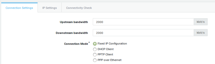
Make sure that the Connection Settings tab is selected (as shown in the image below).
-
Enter the upstream and downstream bandwidth as provided by your ISP (or the value which is applicable in case you select a LAN or DMZ device), e.g.
2000. -
Update your configuration.
Setting |
Description |
|
|---|---|---|
Upstream bandwidth |
This parameter is only relevant if you are using bandwidth management, which must be enabled under System > Feature Activation. The upstream bandwidth is the maximum amount of data which can be sent through the device per second (expressed in Kilobits per second). A value of |
|
Downstream bandwidth |
Only relevant for bandwidth management. The downstream bandwidth is the maximum amount of data which can be received by the device per second (expressed in Kilobits per second). A value of |
|
Connection Modes |
Fixed IP Configuration: Select this option to assign a static IP address to the network device. |
|
DHCP Client: DHCP is an Internet protocol that allows IP addresses to be assigned dynamically by a DHCP server (Defined per RFC 2131). Select this option to dynamically assign an IP address to the device. |
||
PPTP Client (Internet Only): In some countries, Internet Service Providers use PPTP to connect their customers to the Internet. Enter the correct IP and account information. Contact your Internet Service Provider if you are unsure about the account information. |
||
PPP over Ethernet (Internet Only): PPPoE is a network protocol for encapsulating Point-to-Point Protocol (PPP) frames inside Ethernet frames. It is used mainly with ADSL services where individual users connect to the ADSL transceiver (modem) over Ethernet. Contact your ISP if you are unsure about the account information. |
||
Speed / Duplex Mode |
The factory default setting is auto-detect, which negotiates the speed and duplex settings for the highest possible data rates. For this mode to function properly, you must also configure the other endpoint so it uses automatic negotiation as well.
|
|
MTU |
Packet size, often referred to as MTU (Maximum Transmission Unit) is the greatest amount of data that can be transferred in one physical frame on the network. For Ethernet, the MTU is 1500 bytes, for PPPoE 1492, dial-up connections often use 576. 1500 is assumed when no value is specified. |
Creating Bandwidth Definitions
Overview
In this section, we explain how to create Definitions. Definitions allow you to classify the traffic to be regulated by the AXS Guard Bandwidth Management module. Definitions are the largest configuration unit of the Bandwidth Management module and need to be added to a Schema to be functional.
The configuration of Definitions is a three step process; first you need to label the Definition, then create Classes (and Subclasses if necessary). The final step is to create and assign the Filters which shape the traffic to be matched.
Important
- The sum of the guaranteed bandwidth can never exceed 100% of the total available bandwidth. A value must always be specified.
- The maximum bandwidth per Class can never exceed 100% of the total available bandwidth. A value must always be specified.
Labeling the Definition
In this section, we explain how to create a new Definition.
-
Log in to the AXS Guard appliance.
-
Navigate to Network > Bandwidth Management > Definitions.
-
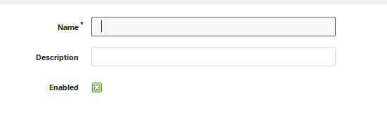
Click on Add New. A screen similar to the image below appears.
-
Enter a name for the Definition (required).
-
Enter a description for the Definition (optional).
-
Make sure the Definition is enabled (default).
-
Start creating your Classes and Subclasses, as explained in the following section.
| Parameter | Description |
|---|---|
Name |
Enter a name for the definition (required). |
Description |
Describe the definition (optional field). |
Enabled |
Check to enable the definition. |
Creating Classes and Subclasses
In this section, we explain how to create Classes and Subclasses. Subclasses are optional. Remember that IPsec has its own Class (ipsec).
Important
- The sum of the guaranteed bandwidth for all Classes can never exceed 100% of the total available bandwidth. A value must always be specified.
- The maximum bandwidth of a Class can never exceed 100% of the total available bandwidth. A value must always be specified.
- The guaranteed and maximum percentages specified for a Subclass have to be considered in relation to the Class, not the total available bandwidth of the network device you are creating the subclasses for.
-
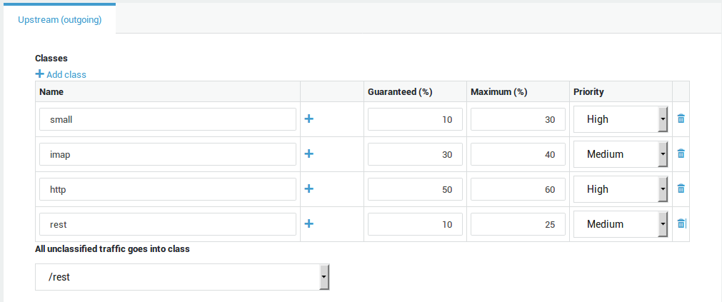
Click on Add Class to create a new Class.
-
Enter a name for the new class. Make sure to a use short, clear name, which reflects the type of traffic you are trying to manage, e.g. mail. Use lower cases only.
-
Enter the guaranteed bandwidth which should be made available for the Class, e.g. 25.
-
Enter the maximum bandwidth which should be made available for the Class, e.g. 50.
-
Select the appropriate priority.
-
If you desire to create one or more Subclasses for a class , click on Add Subclass and enter the name and the values for the guaranteed and maximum bandwidth. Then select the appropriate priority for each Subclass.
-
Repeat the same steps to create additional Classes / Subclasses.
-
Add a rest Class for unclassified traffic.
-
Once you have finished creating all your Classes (and Subclasses), you need to create and assign the Filters to the appropriate Classes or Subclasses. This is explained in the following section.
| Parameter | Description |
|---|---|
Name |
Enter a logical name for the traffic class. A class is a logical unit of traffic with common attributes. A class is composed of filters and can be assigned a priority. The purpose of classes is to allow administrators to keep a clear overview of the divided bandwidth. |
Add subclass |
Click on the |
Guaranteed |
Enter the percentage of guaranteed bandwidth for the given class. The guaranteed bandwidth determines how much bandwidth of the total available bandwidth should be reserved when needed by a specific type of traffic. |
Maximum |
Enter the maximum percentage of bandwidth to be available for the given class (only enforced if the bandwidth is available and not used by other classes). |
Priority |
Select the desired priority (only for subclasses and classes without subclasses). The priority does not affect the amount of allocated bandwidth. The specified maximum is only assigned when network conditions allow it. Classes with the same priority and for which bandwidth remains available, are assigned the remaining bandwidth alternately by the AXS Guard appliance. |
Class for unclassified traffic |
Select a class for all unclassified traffic, i.e. traffic which is likely to exist on your network, but for which no class has been configured. Note: Create a "rest" class for all unclassified traffic. |
Creating Filters
In this section, we explain how to create Filters and assign the Filters to Classes (or optional Subclasses).
Filters are the smallest configuration element of the AXS Guard Bandwidth Management module and specify the properties of the traffic to be regulated.
-
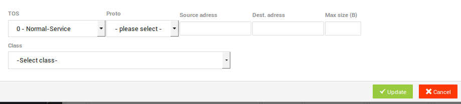
Click on Add Filter.
-
Enter the appropriate settings.
-
Select the Class or Subclass to which the Filter must be assigned.
-
Click on Update when the filter settings are configured.
-
Click on Save to store the new Definition.
| Parameter | Description |
|---|---|
TOS |
Enter the Type of Service to be matched by the filter. The TOS byte in the IP header indicates the purpose of the datagram, e.g. delay, precedence, reliability, minimum cost, throughput etc. The TOS field is now used by Differentiated Services and is called the Diff Serv Code Point or DSCP. |
Proto |
Select the protocol to be matched by the filter. If TCP is selected, you can decide whether or not to match TCP flags. If no flag is selected, the filter will match all TCP packets. In case one or more flags are selected, the filter will only match the packets with the specific flags. |
Source Address |
The source IP address or network range to be matched by the filter. This is an address or address range in your secure LAN or DMZ. Use the CIDR notation to specify a range, e.g. |
Destination Address |
The destination IP address or network range to be matched by the filter. This is an address or address range of an external network. Use the CIDR notation to specify a range, e.g. |
Max Size |
The maximum allowed size of a packet to be matched (expressed in bytes). Packets exceeding the specified size are discarded. A packet of an equal or inferior size is filtered. |
Source Port |
The source port(s) to be matched by the filter. You can specify multiple ports separated by a comma, e.g. |
Destination Port |
The destination port(s) to be matched. You can specify multiple ports separated by a comma, e.g. |
Class |
Assign the filter to the appropriate class. |
Info
- If TCP is selected, more fields will become available. The flag bits are outside the scope of this manual. Please consult the appropriate online resources, RFCs and other TCP documentation for more information.
- To edit existing Definitions, select the desired Definition from the list, then edit and update its settings.
The Definition is now created and ready to be added to a Schema.
Removing Classes, Subclasses and Filters
In this section, we explain how to remove Classes, Subclasses and Filters in case of a configuration error.
-
Navigate to Network > Bandwidth Management > Definitions.
-
Select the definition to be adjusted or corrected.
-
Click on the bin icon to remove undesired classes, subclasses or filters.
-
Update your configuration.
Info
You can also follow steps 1 and 2 to create new Definitions based on existing ones. Select an existing Definition and click on Edit as New.
Assigning Bandwidth Definitions to Schemas
In this section we explain how to configure Schemas. A Definition is only operational if it is added to a Schema.
To configure or add a Schema:
-
Log in to the AXS Guard appliance.
-
Navigate to Network > Bandwidth Management > Schema.
-
Click on the
+sign to add a new schema. -
Configure the schema.
-
Save your configuration.
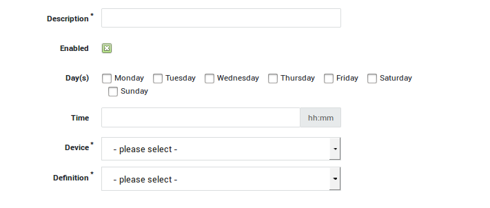
| Parameter | Description |
|---|---|
Description |
A required schema description, e.g. |
Enabled |
Check to enable / uncheck to disable. |
Day(s) |
The days during which the schema is applied. If none are selected and the schema is enabled, it will be applied 7 days a week. |
Time |
The time at which a given definition should start. Use the |
Device |
The network device which is handling traffic for the classes specified in the definition. |
Definition |
Assign a definition to the schema. Go to Network > Bandwidth Management > Definitions for an overview of configured definitions. Note: A special definition |
The Definition(s) are now active. To disable a Schema, navigate to Network > Bandwidth Management > Schema, select the Schema to be disabled from the list and make sure the enabled option is unchecked.
Important
- If no days are selected, the Definition is always active (7 days a week, 24 hours a day).
- A special definition Disable qos can be selected to disable Bandwidth Management during the time/day specified in the scheme.
- To edit an existing Schema, select the desired Schema from the list and change the settings as desired. Click on Update when finished.
Practical Configuration Examples
VoIP Bandwidth Configuration
Overview
In this example, we explain how to configure the Bandwidth Management module to regulate VoIP traffic. The bandwidth of a traditional voice call uses a 64 kbps per session. This means that it is easy to calculate the exact bandwidth which is needed, since all you have to do is multiply the number of phones by 64 kbit/s to determine the minimum guaranteed bandwidth which should be assigned to the VoIP class.
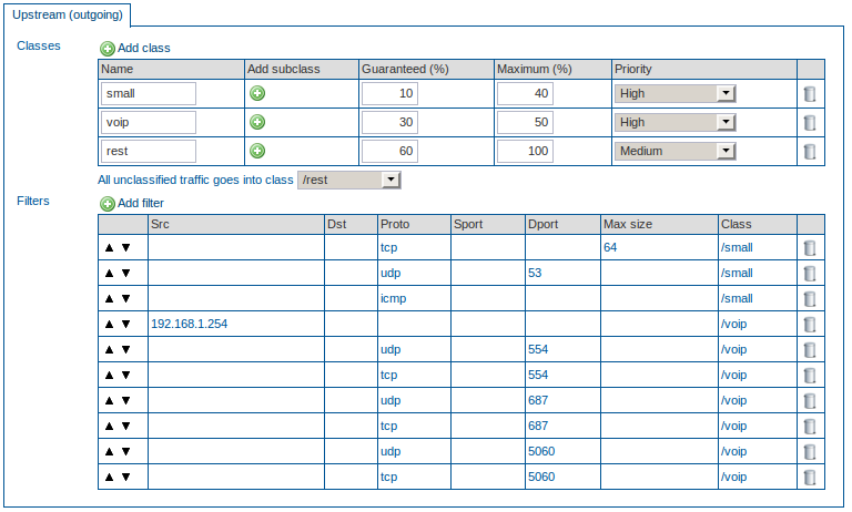
In this example, we assume that your Internet Device has a maximum upstream capability of 1024 kbit/s and that you have a VoIP switchboard to which 5 phones are connected. This means that you have to guarantee at least 64 X 5 kbit/s, in case all phones are used simultaneously (320kbit/s, which is roughly 33% of the total available bandwidth). The switchboard has IP 192.168.1.254/32. VoIP uses various protocols, such as the Real-Time Streaming Protocol (RTSP), which uses UDP or TCP port 554 and the Session Initiation Protocol (SIP), which uses UDP or TCP port 687. The SIP clients typically use TCP or UDP on port numbers 5060 and/or 5061 to connect to SIP servers and other SIP endpoints (5060 is used in this example). In this example we show how all these traffic properties can be defined in individual filters and assigned to a special Class for VoIP.
The other traffic in this example is unclassified and is added to the rest Class.
Creating the VoIP Definition
-
Verify if the maximum upstream and downstream bandwidth have been configured for the network device of which you are about to manage the bandwidth.
-
Create a new Definition.
-
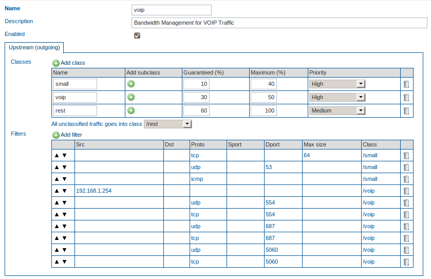
Create a new Class, voip.
-
Guarantee 30% of the total bandwidth to the voip Class. Assign a maximum of 40% to this Class. Set the priority to high.
-
Create a new Class, rest, for the unclassified traffic.
-
Guarantee 60% of the total bandwidth to the rest Class. Assign a maximum of 100% to this Class. Set the priority to medium.
-
Assign all unclassified traffic to the rest Class.
-
Create a new filter with source IP 192.168.1.254/32 and assign it to the voip Class.
-
Create a new filter, select UDP as the protocol type and enter port number 554 (RTSP) as the destination port. Assign this filter to the voip Class.
-
Create a new filter, select TCP as the protocol type and enter port number 554 (RTSP) as the destination port. Assign this filter to the voip Class.
-
Create a new filter, select UDP as the protocol type and enter port number 687 (SIP) as the destination port. Assign this filter to the voip Class.
-
Create a new filter, select TCP as the protocol type and enter port number 687 (SIP) as the destination port. Assign this filter to the voip Class.
-
Create a new filter, select UDP as the protocol type and enter port number 5060 as the destination port. Assign this filter to the voip Class.
-
Create a new filter, select TCP as the protocol type and enter port number 5060 as the destination port. Assign this filter to the voip Class.
-
Save the Definition.
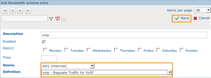
Adding the VoIP Definition to a Schema
-
Create a new Schema.
-
Enter a description for the new Schema.
-
Do not change the default settings.
-
Select the correct network device, i.e. the network device that handles the outgoing VoIP traffic, e.g. eth1.
-
Assign the newly created voip Definition to the Schema.
-
Click on save.
Mail Bandwidth Configuration with Subclasses and Audio Streaming
Overview
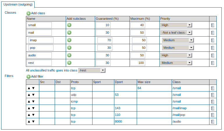
In this example, we explain how to configure the Bandwidth Management module to regulate different types of mail traffic, while ensuring that delay-sensitive traffic , such as audio streaming, is not hindered. In the following example, it is assumed that the clients in your network need access to outside IMAP and POP servers and that IMAP traffic should have priority over POP traffic in case traffic congestion occurs. This can be achieved with Subclasses and by assigning a priority to each Subclass. It is also assumed that network clients need access to audio streaming servers which listen on TCP port 8000.
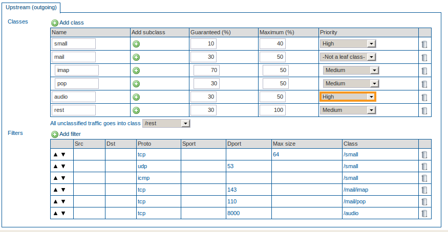
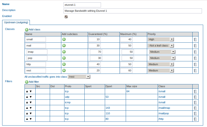
Creating the Mail Definition
-
Verify if the maximum upstream and downstream bandwidth have been configured for the network device of which you are about to manage the bandwidth.
-
Create a new Definition.
-
Create a new Class, mail.
-
Guarantee 30% of the total bandwidth to the mail Class. Assign a maximum of 50% to this Class.
-
Create a new Subclass, imap, by clicking on the + sign next to the mail Class .
-
Guarantee 70% (of the 30% assigned to the mail Class) to the imap Subclass. Enter a maximum of 50%. Set the priority to Medium.
-
Create a new Subclass, pop, by clicking on the + sign next to the mail Class .
-
Guarantee 30% (of the 30% assigned to the mail Class) to the pop Subclass. Enter a maximum of 50%. Set the priority to Medium.
-
Create a new Class, audio, with a guaranteed percentage of 30 and a maximum of 50. Set the priority to high, since this is a delay-sensitive protocol.
-
Create a new Class, rest, for the unclassified traffic.
-
Guarantee 30% of the total bandwidth to the rest Class. Assign a maximum of 100% to this Class. Set the priority to Medium.
-
Assign all unclassified traffic to the rest Class.
-
Create a filter which filters on the TCP protocol and destination port 143. Assign that filter to the /mail/imap Class.
-
Create a filter which filters on the TCP protocol and destination port 110. Assign that filter to the /mail/pop Class.
-
Create a filter which filters on TCP and port 8000. Assign that filter to the audio Class.
-
Save the Definition.
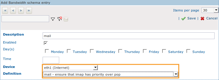
Adding the Mail Definition to a Schema
-
Create a new Schema.
-
Enter a description for the new Schema, e.g. mail.
-
Do not change the default settings.
-
Select the correct network device, i.e. the network device that handles outgoing e-mail traffic.
-
Assign the newly created mail Definition to the Schema.
-
Click on Save.
Managing Bandwidth of an IPsec Device
Overview
In this example, we explain how to configure Bandwidth Management for an IPsec device. All IPsec traffic is routed over an IPsec device, as explained in the AXS Guard IPsec How To. This guide can be accessed by clicking on the permanently available Documentation button in the Administrator Tool. Keep in mind that the guaranteed and maximum bandwidth values entered here inherently apply to all tunnels which depend on the IPsec device, i.e. IPsec and E-tunnels.
-
You cannot set the maximum upstream and downstream bandwidth for an IPsec device directly. When defining a class that will be used in conjunction with IPsec tunnels (e.g. an ESP-based filter to assign guaranteed bandwidth for tunnels), you must name the class ipsec (lower cases). This is a requirement to get the right rates assigned to underlying schemes and definitions.
-
You can only set the maximum upstream and downstream bandwidth for the device which handles the IPsec traffic, e.g. your primary Internet Device.
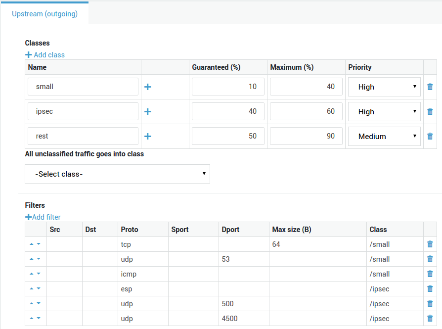
Creating an IPsec Definition
-
Verify if the maximum upstream and downstream bandwidth have been configured for the network device that handles outgoing IPsec traffic, i.e. one of your Internet devices.
-
Create a new Definition.
-
Create a new Class, ipsec. This is a required Class and
mustbe named ipsec. -
Guarantee 40% of the total bandwidth to the ipsec Class. Assign a maximum of 60% to this Class. Set the priority to "high" (also see the note below).
-
Create the following 3 new Filters and assign them to the ipsec Class:
-
One Filter for ESP traffic
-
One Filter for UDP port 500
-
One Filter for UDP port 4500
-
-
Create a new Class, rest, for the unclassified traffic.
-
Guarantee 60% of the total bandwidth to the rest Class. Assign a maximum of 90% to this Class.
-
Save the Definition.
Info
The priority of the ipsec Class should be set in accordance with the protocols that are being tunneled through the IPsec device. Select 'high for response-sensitive protocols, such as VoIP.
Adding the IPsec Definition to a Schema
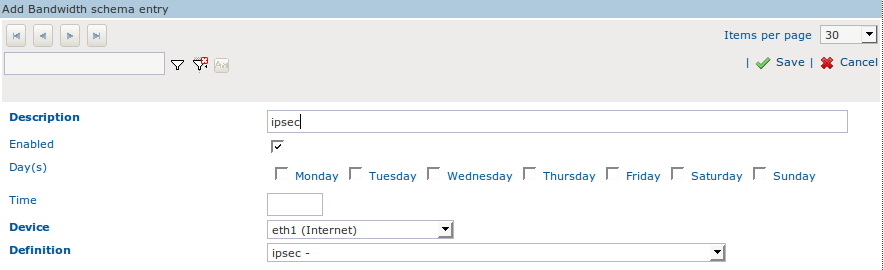
-
Create a new Schema.
-
Enter a description for the new Schema, e.g. ipsec.
-
Do not change the default settings.
-
Select the correct network device, i.e. the network device that handles the outgoing IPsec traffic, e.g. eth1.
-
Assign the newly created ipsec Definition to the Schema.
-
Click on Save.
Managing Traffic within an IPsec Tunnel
Overview
Once you have determined the bandwidth settings of your IPsec traffic, you can regulate traffic within each IPsec tunnel, e.g. traffic going through E-tunnels. For detailed information about IPsec and E-tunnels, see the AXS Guard IPsec How To, which can be accessed by clicking on the permanently available Documentation button in the Administrator Tool.
In the following example, we regulate all IMAP, POP and HTTP traffic going through an E-tunnel. We also illustrate how you can use the Edit as New function to recycle data of any previously configured Definition.
Creating Definitions for Traffic within IPsec Tunnels
-
Verify if the maximum upstream and downstream bandwidth have been configured for the network device of which you are about to manage the bandwidth.
-
Navigate to Network > Bandwidth Management > Definitions and select the Definition created for e-mail.
-
Click on Edit as New.
-
Enter a name for the Definition, e.g. e-tunnel1.
-
Remove any unneeded Definitions.
-
Add a new Class, http and guarantee 40%, enter a maximum of 50%. Set the priority to Medium.
-
Add a new Class, rest for the unclassified traffic and guarantee 20%, enter a maximum of 60%. Set the priority to Medium.
-
Create a new Filter for the http Class. Specify TCP as the protocol and 80 as the destination port.
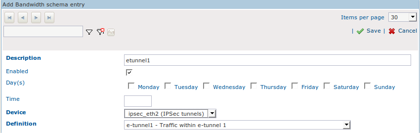
Adding the Definition to the correct IPsec Tunnel
-
Create a new Schema.
-
Enter a description for the new Schema, e.g. e-tunnel1.
-
Do not change the default settings.
-
Select the correct tunnel device, i.e. the IPsec device over which the defined traffic is routed.
-
Assign the newly created Definition, e-tunnel1, to the Schema.
-
Click on Save.
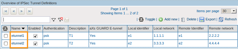
Multi-layered Setups with IPsec Tunnels (E-tunnels)
We wish to manage and balance:
-
The total bandwidth of the Internet device used for IPsec, e.g. eth1.
-
The total bandwidth of the IPsec device used by both e-tunnels, e.g. ipsec_eth1.
-
The network traffic going through each e-tunnel, based on protocols, destination IP addresses or any other traffic properties.
Four Schemas are required to accomplish this result.
Issues
-
You need to create a Definition with a required ipsec Class and assign it to your Internet device, e.g. eth1. If the Class is given any other name, other Schemas will not be assigned the correct proportional bandwidth, e.g. with an upstream of 100Mbit, assigning 50% to the ipsec class ensures that others Schemas have 50 Mbit available. When using a different name this is not the case.
-
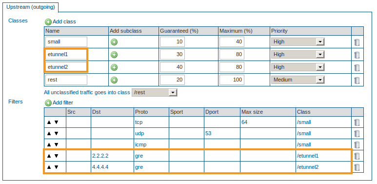
You need to create a Definition for the e-tunnels (filtering on GRE traffic and destination IP address) and assign this Definition to the ipsec device. The name of each e-tunnel Class has to be identical to the name of its e-tunnel, otherwise the correct proportional bandwidth will not be assigned (analogy to eth1).
-
You need to create a Definition for the traffic going through e-tunnel1, e.g. IMAP, SMTP, VoIP, etc.
-
You need to create a Definition for the traffic going through e-tunnel2, e.g. IMAP, HTTP, POP, etc.
Configuration
-
Configure your e-tunnels as explained in the AXS Guard IPsec How To, which is accessible by clicking on the permanently available Documentation button in the Administrator Tool.
-
Create an IPsec Definition. Use the
ipsecClass. -
Add the IPsec Definition to a Schema and the desired Internet device (e.g. eth1).
-
Create a Definition for the e-tunnels. Create a Class with the same name of the 1st e-tunnel and filter on GRE traffic and destination IP address. Add another Class with the same name of the 2nd e-tunnel and filter on GRE traffic and destination IP address.
-
Add the newly created Definition to a Schema and the IPsec device.
-
Create a new Definition for traffic going through e-tunnel1.
-
Add this Definition to a Schema and the correct e-tunnel device handling the traffic.
-
Create a new Definition for traffic going through e-tunnel2.
-
Add this Definition to a Schema and the correct e-tunnel device handling the traffic.
Important
The name of the e-tunnel Classes have to be identical to the name of the e-tunnels, otherwise the bandwidth will not be assigned proportionally.
Bandwidth Management Status
Overview
The bandwidth management status screen provides information about:
-
The last time a definition was edited.
-
A table view of active classes, including their guaranteed and maximum bandwidth.
-
The amount of transmitted bytes per class.
-
A graph, showing the averages of outgoing traffic per class and the total average over an 8-hour period. Use this graph to look for unusual traffic peaks and adjust bandwidth management where needed.
Accessing the Status
-
Log in to the AXS Guard appliance.
-
Navigate to Network > Bandwidth Management > Status.
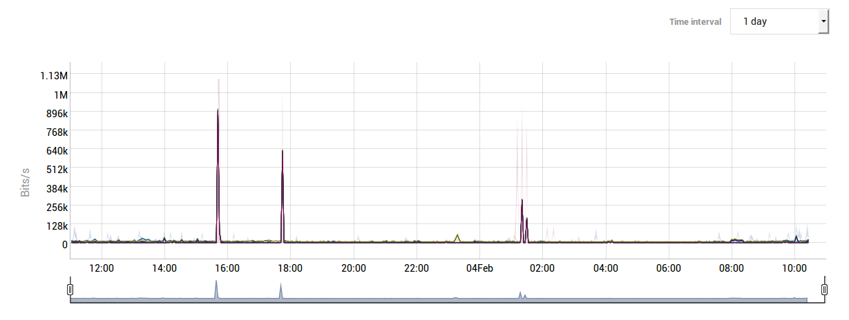
Analyzing Unusual Traffic Peaks
If you are monitoring the status of the AXS Guard Bandwidth Management module and suspect that a given traffic Class is generating unusual peaks, you can access the AXS Guard console and run the iftop command. This command allows you to analyze current network traffic on any AXS Guard network device.
Information about accessing the AXS Guard console and using the iftop command is provided in the AXS Guard CLI How To, which can be accessed by clicking on the permanently available Documentation button in the Administrator Tool.
Troubleshooting
How do I increase the available bandwidth of a network device?
The maximum available bandwidth of a network device depends on its hardware specifications and cannot be exceeded. To increase your Internet bandwidth, you must contact your ISP. Entering higher values than the ones supported by your hardware or Internet service provider will lead to undesired behavior.
An error message occurs when I try to add a Definition to a Schema
You cannot enable a bandwidth Schema on a device without configuring the bandwidth settings (upstream and downstream) of that device. If you are unsure about the values to enter for your Internet devices, contact your ISP.
How do I allow multiple Definitions within a given time frame?
Add the desired Definition to separate Schemas and enter the desired start time of each Schema.
How to I specify a stop time for a Definition?
See above. Create the desired Definitions and add them to separate Schemas. Specify the start time for each Schema.
Bandwidth Management checklist
-
The available bandwidth of a device needs to be configured correctly before you can manage its bandwidth.
-
The sum of guaranteed bandwidth for all Classes may not exceed 100% of the total available bandwidth.
-
Each Class (and Subclasses if applicable), requires a guaranteed and a maximum percentage.
-
You should create a separate Class for unclassified traffic, e.g. a rest Class. In turn, all unclassified traffic should be assigned to the rest Class.
-
The ipsec Class affect all IPsec tunnels and E-tunnels. This Class is required to regulate IPsec traffic.
-
All Classes (and Subclasses if applicable), must be composed of at least one Filter.
-
Each Filter must contain the correct properties to be matched.
-
The enabled option must be checked in the Definition, as well as the Schema.
I am detecting unusual network traffic peaks.
You can analyze current traffic of any AXS Guard network device by accessing the AXS Guard console and executing the iftop command.
Support
If you encounter a problem
If you encounter a problem with AXS Guard, follow the steps below:
-
Check the troubleshooting section of the feature-specific manual.
-
Check the knowledge base on this site for information about special configurations.
-
If no solution is available in any of the above sources, contact your AXS Guard vendor.
Contact Information
(+32) 15-504-400
support@axsguard.com