IPsec Server
Introduction
About this Document
This document serves as a reference and practical resource for technical personnel and system administrators. In this guide, we explain how to configure the AXS Guard IPsec server.
Examples used in this Guide
All setups and configuration examples in this guide are executed at an advanced administrator level. Some options may not be available if you log in as a full administrator or a user with lower access privileges.
As software development and documentation are ongoing processes, the screenshots shown in this guide may slightly deviate from the current user interface.
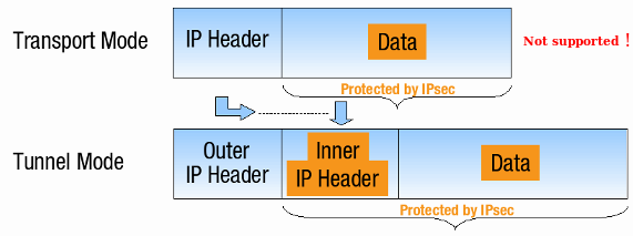
Tunnel vs. Transport Mode
IPsec can be used in two modes: Tunnel Mode or Transport Mode, as illustrated below.
AXS Guard only supports IPsec in Tunnel Mode. This has to be taken into consideration when connecting other UTM appliances or clients to AXS Guard.
Security Modes: AH vs. ESP
| Security Mode | Description | Supported |
|---|---|---|
| AH (Authentication Header) | Provides data integrity and origin authentication for packets. | No |
| ESP (Encapsulating Security Payload) | Encrypts the entire payload of the IP packet, ensuring both data confidentiality and data integrity. | Yes |
Required Protocols & Ports
Internet Firewall Settings
| Protocol | Port | Description |
|---|---|---|
| IKE | UDP 500 | Used by the Internet Key Exchange (IKE) protocol to establish a secure connection between devices for the VPN. |
| ESP | IP Protocol 50 | Identifies traffic encrypted using the Encapsulating Security Payload (ESP) mode, the only mode supported by AXS Guard for IPsec. AH (Authentication Header) mode is not supported. |
| UDP | 4500 | Used for Network Address Translation (NAT) traversal, which allows VPN connections to work even behind devices that use NAT. |
LAN Firewall Settings
AXS Guard simplifies your IPsec setup by automatically creating firewall rules when you define a tunnel. However, there are two main tunnel types to consider: Common IPsec tunnels and e-tunnels (GRE over IPsec). These require slightly different configuration approaches.
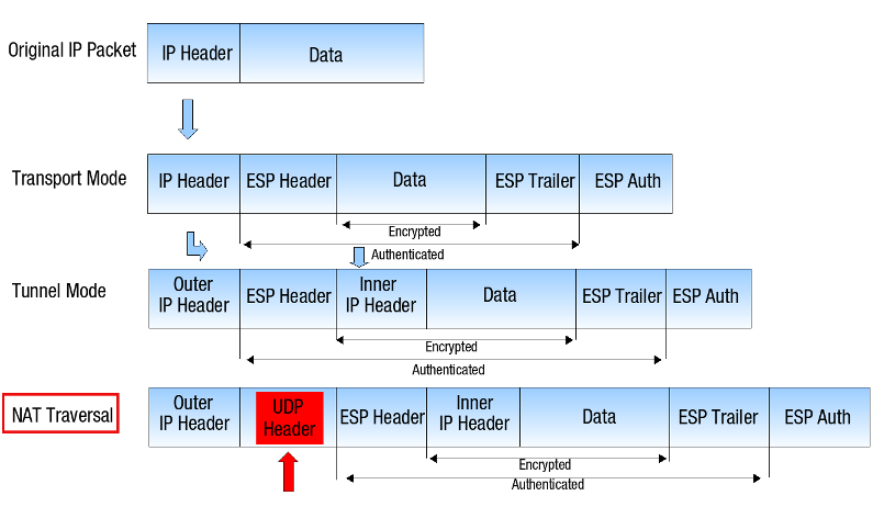
NAT-Traversal & PAT
Any attempt to perform NAT/PAT operations on IPsec packets creates issues because IPsec authenticates all packets in Tunnel Mode. This authentication necessitates that packets remain unaltered to preserve data integrity.
NAT-Traversal inserts a UDP header with destination port 4500 right before the ESP header. The inserted UDP header can be translated (modified), while keeping the original IP header intact. This ensures that the packet can reach its final destination without any issues.
Connection Identifiers & NAT-T
When using NAT-T, a common issue can arise regarding connection identifiers. Here's why:
- The Problem: Imagine a device behind a NAT device trying to connect to another device using an IPsec tunnel. The device behind the NAT might use its private IP address (local identifier) to identify itself.
- Mismatch and Rejection: The receiving device, however, only sees the external IP address. Since IPsec requires both sides to have matching connection identifiers, the receiving device will reject the connection due to this IP address mismatch and an authentication failure will appear in the IPsec server logs.
To avoid this issue, we highly recommend using custom identifiers when configuring IPsec tunnels with NAT-T. These custom identifiers should be the same on both sides of the connection and not be based on internal IP addresses.
- Forcing NAT-Traversal may be necessary even when the peers are not NAT’d, e.g. when a router is not properly forwarding ESP packets.
- For additional details about NAT-Traversal, see RFC 3715.
Tunnel Types
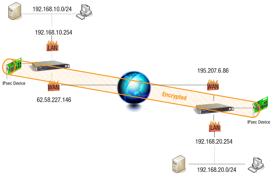
Common IPsec Tunnels
AXS Guard automatically creates firewall rules within the stat-vpn policy for the subnets defined in a tunnel configuration. Here's a breakdown of the automatically generated firewall rules based on the illustration below:
-
AXS Guard #1
62.58.227.146-
ipsec_tunnel_r1: On any ACCEPT 192.168.10.0/24 > 192.168.20.0/24
-
ipsec_tunnel_r2: On any ACCEPT 192.168.20.0/24 > 192.168.10.0/24
-
-
AXS Guard #2
195.07.6.86-
ipsec_tunnel_r1: On any ACCEPT 192.168.20.0/24 > 192.168.10.0/24
-
ipsec_tunnel_r2: On any ACCEPT 192.168.10.0/24 > 192.168.20.0/24
-
Note
If you modify your local or remote network settings, the associated firewall rules will be adjusted automatically to match the new configuration.
E-tunnels (GRE over IPsec)
E-tunnels, also known as GRE over IPsec tunnels, require slightly different firewall rules compared to standard IPsec tunnels. These tunnels make use of a virtual network interface called an e-tunnel device. Think of it as a software-created network adapter that doesn't have a physical counterpart.
For e-tunnels, AXS Guard automatically configures firewall rules within the stat-etunnel policy. These rules are based on the tunnel definition and the virtual IP addresses assigned to the e-tunnel devices. We'll delve deeper into these rules based on the illustration provided below.
-
AXS Guard #1
62.58.227.146- etunnel_X: On any ACCEPT 10.10.10.2/32 > 10.10.10.1/32
-
AXS Guard #2
195.07.6.86- etunnel_X: On any ACCEPT 10.10.10.1/32 > 10.10.10.2/32
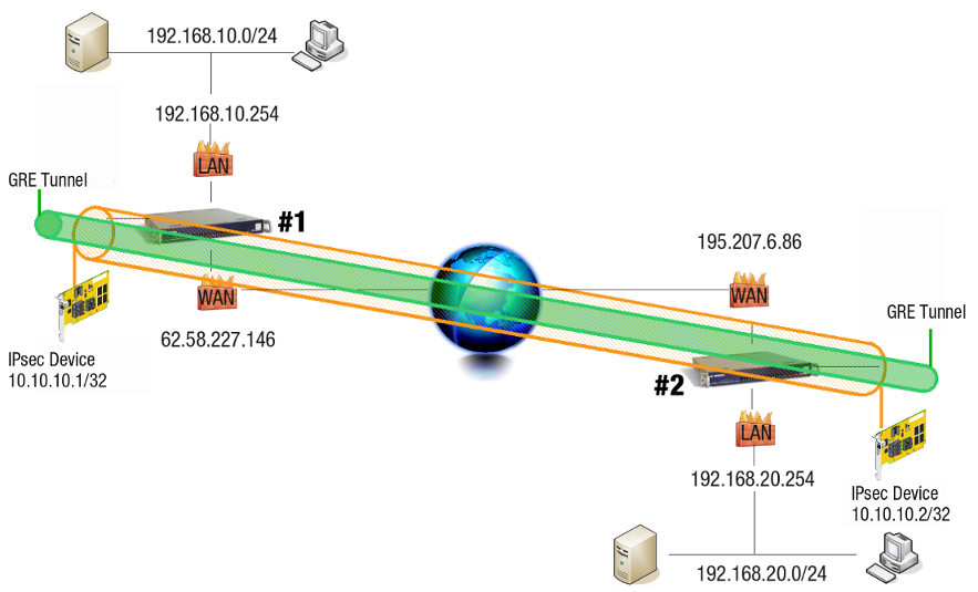
When you configure routing entries to connect the subnets as shown in the illustration above, AXS Guard automatically adds the following firewall rules to the stat-vpn policy.
-
AXS Guard #1
62.58.227.146-
axs2_r1: On any ACCEPT 192.168.10.0/24 > 192.168.20.0/24
-
axs2_r2: On any ACCEPT 192.168.20.0/24 > 192.168.10.0/24
-
-
AXS Guard #2
195.07.6.86-
axs1_r1: On any ACCEPT 192.168.20.0/24 > 192.168.10.0/24
-
axs1_r2: On any ACCEPT 192.168.10.0/24 > 192.168.20.0/24
-
E-tunnel Subnet Routing and Firewall Rules
- Firewall rules for specific subnets are only added if the appropriate routing entries are made, in contrast to common IPsec tunnels. These firewall rules should be adjusted according to your needs and won't automatically update if subnets or routes change. Manual adjustments might be required in such cases.
- Additionally, firewall rules for any network alias added to a secure device, such as
eth0, are not automatically included. They must be configured manually. For detailed information, refer to the section about e-tunnels & aliases and the troubleshooting section.
IP Aliasing
The previous section explained how automatically generated firewall rules are added to the stat-vpn policy when routing entries are configured for subnet connections. However, it's important to note that these rules only apply to the specific subnets defined in the tunnel configuration.
IP aliasing on AXS Guard does not automatically generate firewall rules for traffic originating from any alias added to a secure device (such as eth0). If you need to allow traffic from such aliases through an e-tunnel, you will need to create those rules manually. The following example will provide a detailed explanation of how to achieve this.
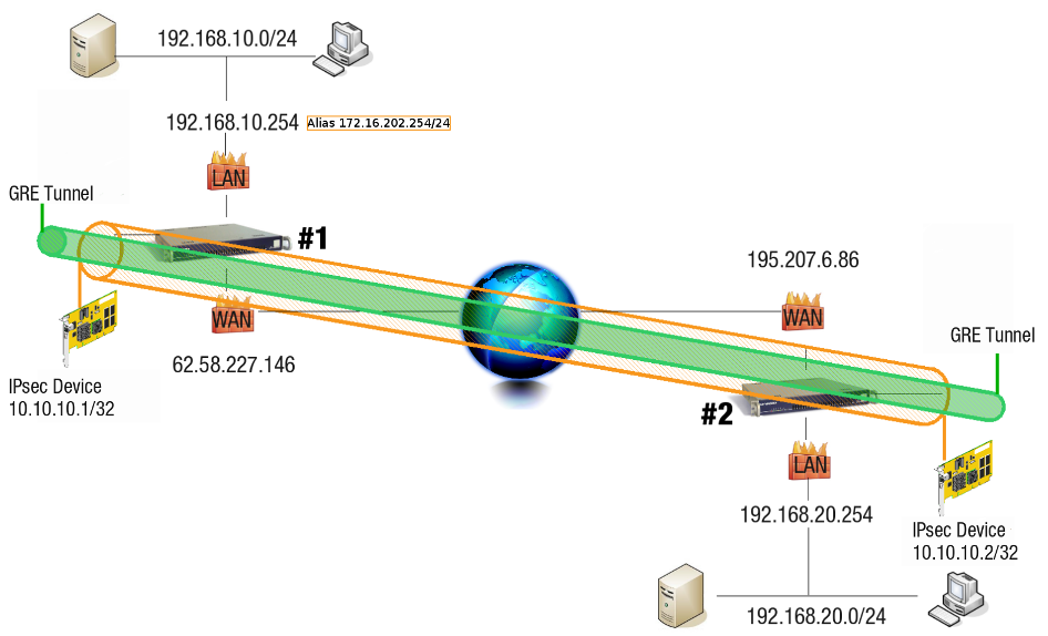
Adding a route for the destination network 192.168.20.0/24 on AXS Guard #1 via an e-tunnel automatically adds the the following firewall rules:
-
r1 On any ACCEPT 192.168.10.0/24 > 192.168.20.0/24
-
r2 On any ACCEPT 192.168.20.0/24 > 192.168.10.0/24
This means that network traffic originating from 172.16.202.0/24 cannot be sent to 192.198.20.0/24, since the associated firewall rules are not created. The firewall rules must be added manually (see configuration examples).
Based on the illustration above, the following firewall rules must be added on AXS Guard #1.
-
r1 On any ACCEPT 172.16.202.254/24 > 192.168.20.0/24
-
r2 On any ACCEPT 192.168.20.0/24 > 172.16.202.254/24
On AXS Guard #2, add the necessary routing entries towards 192.168.10.0/24 and 172.16.202.0/24.
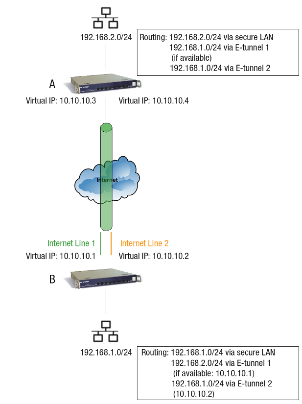
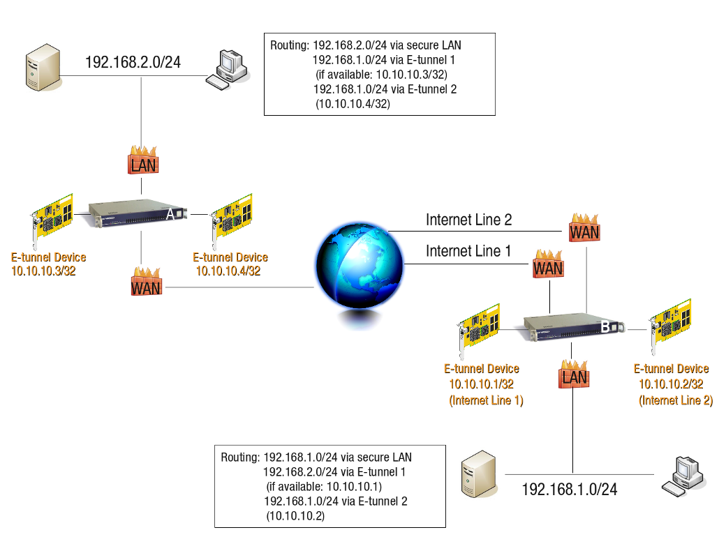
VPN Failover
E-tunnels are a highly recommended approach for setting up VPN failover when your remote AXS Guard appliance has redundant internet lines. To achieve this failover functionality, administrators need to follow these steps:
- Create Separate Tunnel Definitions: Define separate tunnels for both the primary and failover connections.
- Add Route for Failover: Configure an additional route on the local AXS Guard that points to the remote AXS Guard via the alternate internet line.
- Assign Priority: Assign a higher priority to the primary tunnel definition compared to the failover tunnel.
- Enable Dead Peer Detection: Enable Dead Peer Detection on both the local and remote AXS Guard units.
With this configuration, if the main internet line fails on the remote AXS Guard, e-tunnel traffic will automatically reroute through the alternate internet line according to the additional route you defined. As shown in the image, you'll typically have two tunnel definitions on both AXS Guard A and AXS Guard B, each with unique virtual IP addresses.
XAUTH
The IPsec protocol with XAUTH can be used to set up an AXS Guard VPN server for remote users connecting over the internet. This is commonly referred to as a "Road Warrior" configuration, where the VPN client is typically a laptop.
With XAUTH, Road Warrior users are required to provide additional credentials beyond just a pre-shared key or client certificate to establish a secure connection. This adds an extra layer of security for remote access.
For detailed setup instructions on configuring XAUTH for Road Warrior access, refer to the IPsec XAUTH How To guide.
IPsec Configuration
Feature Activation
-
Log in to your AXS Guard appliance.
-
Go to System > Feature Activation > VPN
-
Enable
Do you use VPN IPsec?and update your configuration.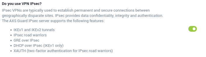
Info
As soon as you enable the IPsec feature, AXS Guard will automatically start to generate RSA keys required for authentication. This process may take a while, especially on virtual appliances. Please be patient.
Server Settings
Appliances without Internet Redundancy
-
Navigate to VPN > IPsec > Server.
-
Enter the settings as explained in the tables below.
-
Click on Update.
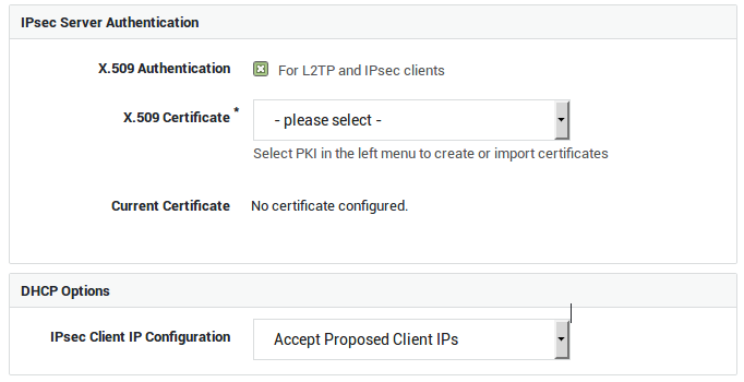
| Option | Description |
|---|---|
X.509 Authentication |
Enable this option if you intend to configure IPsec tunnels for L2TP and other IPsec clients (XAUTH). The X.509 certificate is used by the IPsec server to identify itself to IPsec clients, a.k.a. road warriors. Go to PKI > Certificates to import or create certificates for the IPsec server and its clients. |
Server Certificate |
Select the appropriate server certificate. Go to PKI > Certificates for an overview of available certificates or to create or import a new server certificate. |
| Option | Description |
|---|---|
IPsec Client IP Configuration |
Select whether or not IPsec clients should obtain an IP address from a DHCP server in your network. |
DHCP Server IP |
This field is only visible if you selected to use DHCP for IPsec clients. Enter the IP address of a DHCP server in your secure LAN. |
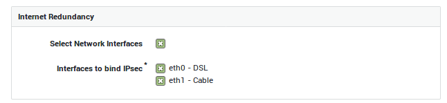
Appliances with Internet Redundancy
If Internet Redundancy is enabled on your appliance, i.e. if your appliance has two or more Internet connections, you can select which Interface(s) should handle(s) IPsec traffic. Select all interfaces if you wish to configure a failover setup.
-
Navigate to VPN > IPsec > Server.
-
Enter the settings as explained in the tables below.
-
Click on Update.
| Option | Description |
|---|---|
Select Network Interfaces |
This option is only available if Internet redundancy is enabled on your system. Check to specify the network interfaces that should handle IPsec traffic. |
Interfaces to bind IPsec |
This field only appears if your enabled the previous option. Select the network interfaces to be used by the IPsec server. You can only select Internet interfaces; DMZ interfaces cannot be selected. |
IKE & ESP Profiles
In this section, we explain how to configure IKE (Phase 1) and ESP (Phase 2) profiles on AXS Guard. These profiles determine:
-
The encryption algorithms to be used.
-
The authentication algorithms to be used.
-
The Diffie-Hellman Group to be used.
AXS Guard offers predefined IKE and ESP profiles for your convenience. These profiles come with pre-configured security settings and cannot be modified directly. However, you can easily create a custom profile based on a predefined one (edit as new).
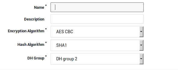
Creating IKE Profiles
-
Navigate to VPN > IPsec > IKE Profiles.
-
Click on Add New.
-
Enter the IKE settings as explained in the table below.
-
Click on Save.
Tip
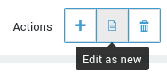
Edit as new allows you to create a new IKE profile based on a predefined IKE profile.
| Option | Description |
|---|---|
Name |
Enter a name for your IKE profile. This name will appear in the IKE profile drop-down menu when you configure an IPsec tunnel. |
Description |
Enter a description for the new IKE profile. Even though this is an optional field, we recommend using a sensible name to facilitate the configuration of your IPsec tunnels. The description will also appear in the IKE profile drop-down menu when you configure or edit a tunnel. |
Encryption Algorithm |
Select the desired encryption algorithm in the drop-down menu. Note that the selected encryption algorithm must match the one of the other endpoint to successfully establish a tunnel. |
Hash Algorithm |
Select the desired hash algorithm in the drop-down menu. Note that the selected algorithm must match the one of the other endpoint to successfully establish a tunnel. |
DH Group |
Select the appropriate Diffie-Hellman Group in the drop-down menu. Note that the selected group must match the group of the other endpoint in order to successfully establish a tunnel. |
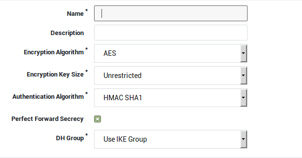
Creating ESP Profiles
-
Navigate to VPN > IPsec > ESP Profiles.
-
Click on Add New.
-
Enter the settings as explained in the table below.
-
Click on Save.
Tip
Edit as new allows you to create a new ESP profile based on a predefined ESP profile.
| Option | Description |
|---|---|
Name |
Enter a name for your ESP profile. This name will appear in the ESP profile drop-down menu when you configure an IPsec tunnel. |
Description |
Enter a description for the new ESP profile. Even though this is an optional field, we recommend using a sensible name to facilitate the configuration of your IPsec tunnels. The description will also appear in the ESP profile drop-down menu when you configure or edit a tunnel. |
Encryption Algorithm |
Select the desired encryption algorithm in the drop-down menu. Note that the selected encryption algorithm must match the one of the other endpoint to successfully establish a tunnel. |
Encryption Key Size |
Select the desired key size for the encryption algorithm. The number of available key sizes depends on the selected encryption algorithm. |
Authentication Algorithm |
Select the desired hash algorithm in the drop-down menu. Note that the selected algorithm must match the one of the other endpoint to successfully establish a tunnel. |
Perfect Forward Secrecy |
Check to enable Perfect Forward Secrecy (PFS). If PFS is enabled, a new Diffie-Hellman exchange is performed with each Quick Mode (Phase 2) negotiation, providing keying material with a greater entropy, meaning it is more resistant to cryptographic attacks. Note that both sides of the VPN must be able to support PFS in order for PFS to work. |
DH Group |
Select the appropriate Diffie-Hellman Group in the drop-down menu. Note that the selected group must match the group of the other endpoint in order to successfully establish a tunnel. |
Creating a New Tunnel
-
Navigate to VPN > IPsec > Tunnels
-
Click on Add New.
-
Enter the tunnel parameters as explained in the following sections.

Mind the difference between:
- RSA Authentication (Only applies to site-to-site tunnels)
- PSK Authentication (Applies to site-to-site tunnels, IPsec road warriors and L2TP clients)
- X.509 Authentication (Only applies to IPsec road warriors and L2TP clients)
Tunnel Type & Interfaces
Option |
Description |
|---|---|
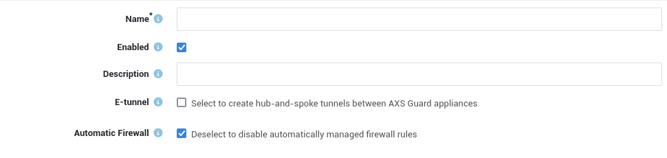
Name |
Enter a name to reference the IPsec tunnel, using lower cases without spaces. Names of e-tunnels should not exceed 13 characters. The tunnel name will appear in the tunnel overview. |
Enabled |
Enables the IPsec tunnel. Uncheck to disable. |
Description |
Descriptions are optional, but useful if you have a lot of tunnels to manage. Even though this is an optional field, we recommend using a sensible name to facilitate the configuration and management of your IPsec tunnels. The description will also appear in the tunnel overview. |
Interface |
This option is only available if Internet Redundancy is enabled on your appliance, i.e. for appliances with two or more Internet devices. Select the interface that should handle traffic for your IPsec tunnel. Note that only Interfaces which have been selected under IPsec > Server are offered as an option. Selecting the default option means that the first Internet device will be used. |
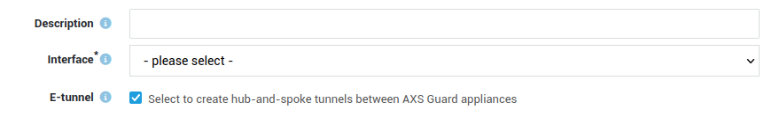
E-tunnel |
Select this option to create hub-and-spoke tunnels between AXS GUARD appliances. E-tunnels allow you to easily connect remote networks by adding static routes to each tunnel endpoint. E-tunnels use GRE (defined per RFC 2784) over IPsec. An IP address must be assigned to each virtual endpoint (GRE device) of the e-tunnel. With e-tunnels, one AXS GUARD appliance acts as the central site router, to which all the other sites connect through IPsec. By adding static routes, all sites are able to reach the main network behind the central router and each other’s networks via the tunnel to the central AXS GUARD appliance. Go to Network > Routing to connect networks via e-tunnels. E-tunnels can also provide redundancy. Failure of a main tunnel is automatically detected by the IPsec framework which automatically switches to a secondary tunnel, if available. In a High Availability environment, where master and slave units are used, the master unit can function as a primary tunnel endpoint, whereas the slave unit can function as an endpoint for the secondary tunnel. |
Automatic Firewall |
When enabled, the AXS Guard appliance will automatically create, update and delete firewall rules for the tunnel. If you wish to create your own firewall rules, disable this option. |
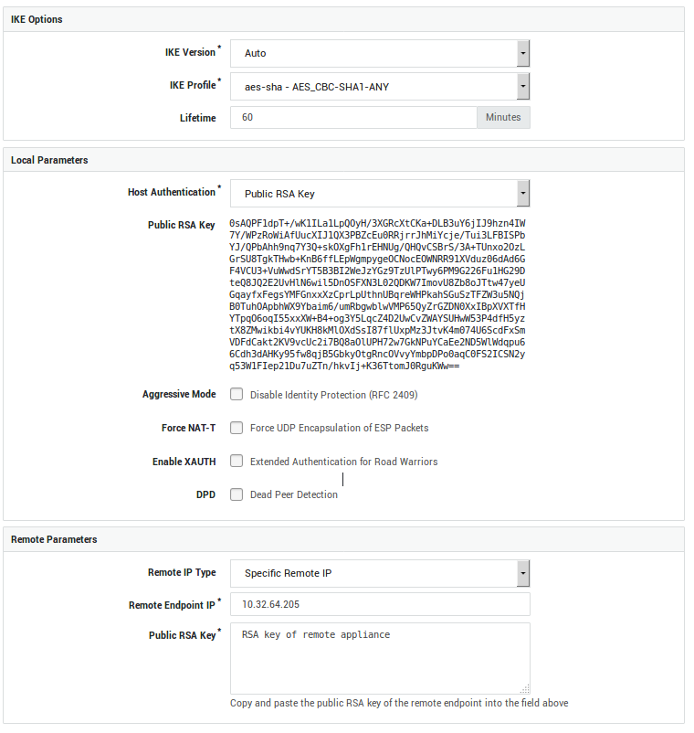
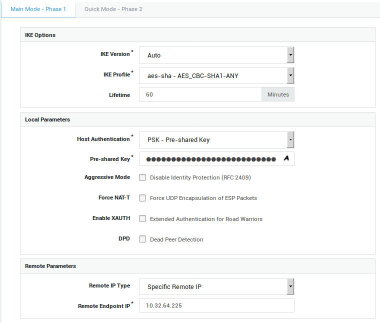
Phase 1 - Main Mode (IKE)
Option |
Description |
|---|---|
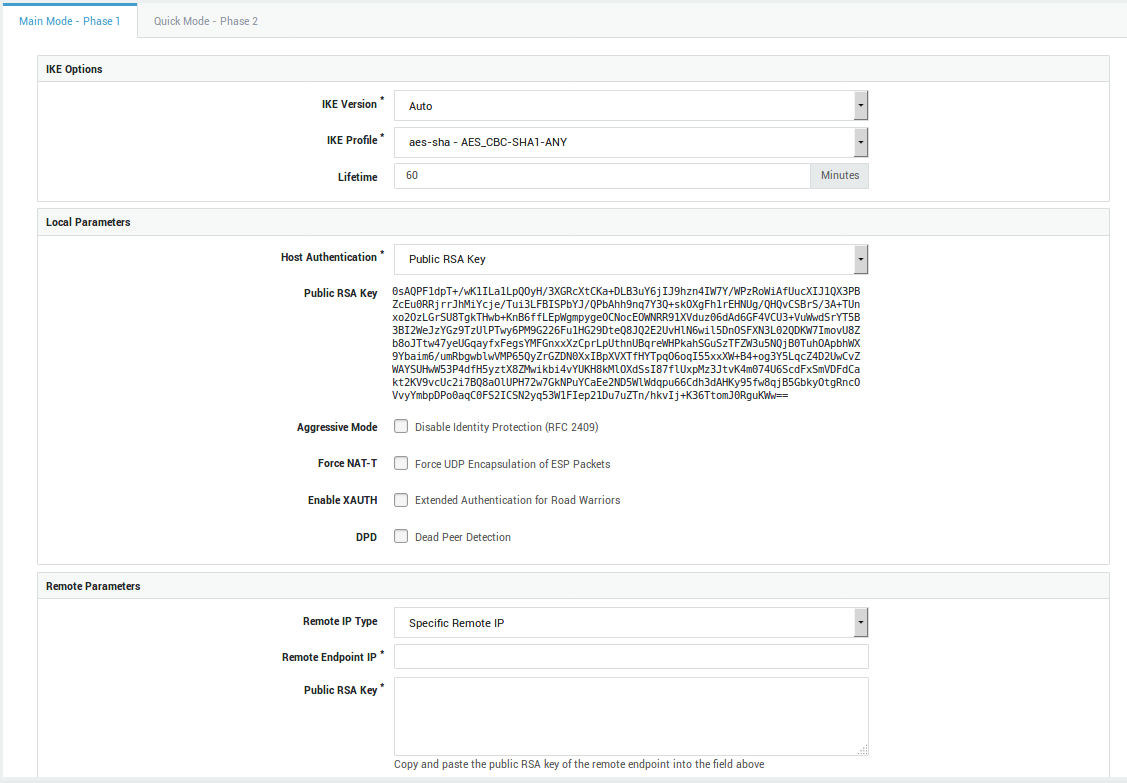
IKE Profile |
Select the IKE profile to be used with by your tunnel. Only profiles created under IPsec > IKE Profiles are available for selection. The options of the selected profile must match those of the other endpoint. |
IKE Version |
Select the appropriate IKE version. The selected version must match that of the other endpoint. |
Lifetime |
This option specifies how long the keying channel of a connection (ISAKMP SA) should last before being renegotiated. Values can range from 19 minutes as a minimum, up to 480 minutes as a maximum. The default value is 60 minutes and can differ on both endpoints. |
Option |
Description |
|---|---|
Host Authentication |
A key or certificate is used by the IPsec server to prove its identity to hosts and to allow these hosts to verify its identity. Select the appropriate option for your IPsec tunnel:
|
Public RSA Key |
Select to use IPsec authentication by means of public RSA keys. Both sides of the tunnel have their public/private RSA key infrastructure installed. The endpoints exchange their public keys, which enables them to encrypt and decrypt messages. There are some extra constraints with this type of authentication; a Base64-encoded key of a least 2192 bits is required. The keys should be generated in the same way on both endpoints. The local public RSA key will automatically appear on screen if you select this option. Copy and paste this key to the remote endpoint. Be careful not to add extra spaces or characters during this process. |
RSA Key Size |
This field is only visible if you selected Public RSA Key authentication and a value lower than 2192 bits has been configured in previous versions of the software. 2192 bits is the supported minimum. Select the strength of the RSA key pair to be used on this end of the tunnel. 4096 bits is the system default and recommended key size. Caution: When selecting a higher key size, you must copy the updated public key to the remote endpoint, otherwise the connection will fail. Lowering the key size is not possible. |
PSK |
Select to use IPsec authentication by means of a pre-shared key (PSK). This is a unique key that is known by both endpoints and consists of a string of characters. When using PSK with Aggressive Mode, the authentication hash is transmitted as a response to the initial packet of the host that wants to establish an IPsec tunnel. The hash (pre-shared key) is not encrypted. If attackers can capture these session packets, they can run an attack to recover the PSK. The attack only affects aggressive mode because main mode encrypts the hash. Be aware that there are security tools that make these attacks simple to execute, e.g. ikescan. |
Pre-shared Key |
This field only appears if you selected PSK authentication. Enter your pre-shared key into this field. From a security perspective, it is highly recommended to use a strong, complex shared secret combined with Perfect Forward Secrecy (PFS). Complex secrets are less susceptible to brute-force attacks, while PFS ensures that the same data encryption key will not be regenerated (increased entropy). Note that the string must be identical on both sides of the IPsec tunnel and must be kept secret at all times. If you suspect that a key has been compromised, it must be changed immediately. Click on the "A" after the input field to display the input as you type. Best Practices for PSKs
|
X.509 Certificate |
A prerequisite for this type of authentication to work, is to configure the PKI infrastructure of the AXS GUARD appliance. The CA must be initialized, a server certificate must be imported or created and installed under IPsec > Server. Server, L2TP and IPsec client certificates can be created under PKI > Certificates and distributed among peers. L2TP is a typical Road Warrior setup which uses this kind of authentication; the AXS GUARD appliance listens for incoming connections from clients which have been issued a valid client certificate. The certificate is used to setup the encrypted IPsec tunnel. The L2TP protocol is used to authenticate the client a second time by means of a username and password, such as a one-time password generated by a DIGIPASS token. |
Current Certificate |
This read-only field only appears if you selected X.509 host authentication and displays information about the selected X.509 certificate. |
Aggressive Mode |
Check to use Aggressive Mode instead of Main Mode. Aggressive Mode is less secure and vulnerable to Denial of Service (DoS) attacks. It is also vulnerable to brute-force attacks with software such as ikecrack. Its use should be avoided, especially with XAUTH and PSK. Aggressive Mode is limited to only one proposal; there is no room for negotiation. |
Force NAT-T |
In some cases, for example when ESP packets are filtered or when a broken IPsec peer fails to recognize NAT, it can be useful to force RFC 3948 encapsulation. This option forces the NAT detection code to lie and tell the remote peer that RFC-3948 encapsulation (ESP in UDP port 4500 packets) is required. |
Enable XAUTH |
Extended authentication or XAUTH provides an additional level of authentication (in addition to the host authentication) in that the IPsec endpoint requests user credentials before any data transfer can take place. It is an extension of the IPsec phase1 authentication provided by IKE. Enable this option if you wish to enforce two-factor authentication for IPsec clients by means of DIGIPASS tokens. Go to Authentication > Services to configure the XAUTH authentication policy. |
DPD |
Check to enable dead peer detection, which continuously tests whether the tunnel is still up. |
Delay |
If DPD is enabled, you can specify the interval between tests. The system default interval is 30 seconds. |
Timeout |
If DPD is enabled, you can specify the maximum amount of time to wait for peer responses before they are considered dead. The system default value is 120 seconds. |
Option |
Description |
|---|---|
Remote IP Type |
You can either specify the IP address of the remote endpoint, allow any remote IP address or specify a hostname. |
Remote Endpoint IP |
Enter the public IP address of the remote endpoint. |
Remote Endpoint Hostname |
Enter the public hostname of the remote endpoint, e.g. |
Public RSA Key |
This field is only visible if you selected Public RSA Key authentication. Copy and paste the public RSA key of the remote endpoint into this field. Only Base64-encoded keys are accepted. |
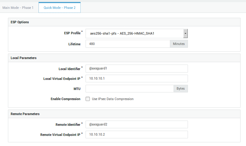
Phase 2 - Quick Mode (ESP)
Option |
Description |
|---|---|
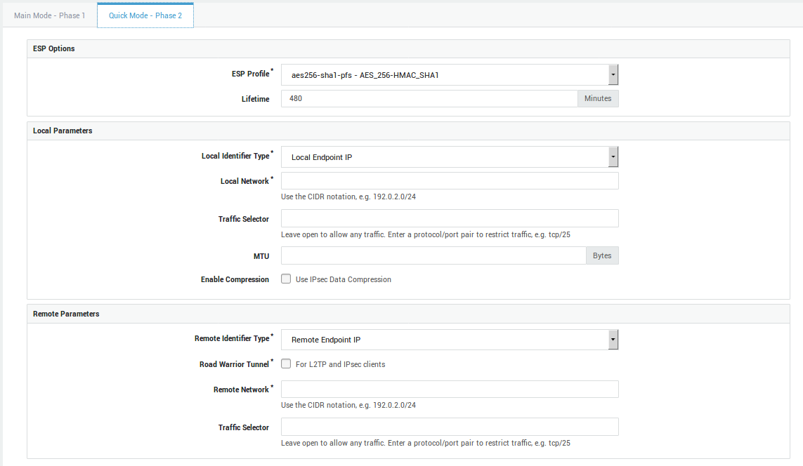
ESP Profile |
Select the ESP profile to be used by your tunnel. It includes both a hash and an encryption algorithm which are used to encrypt all data going through the IPsec tunnel. Only profiles created under IPsec > ESP Profiles are available for selection. The options of the selected profile must match those of the other endpoint. |
Lifetime |
This value specifies how long a particular instance of a connection (a set of encryption/authentication keys for user packets, otherwise referred to as IPsec SA) should last, from successful negotiation to expiry. Values can range from 5 minutes as a minimum, up to 1440 minutes as a maximum. The default value is 480 minutes. This value can differ on both sides of the connection. |
Option |
Description |
|---|---|
Local Identifier Type |
Choose a method for the local side to identify itself to the remote side of the connection, either by means of the local endpoint IP or by means of a custom identifier. The latter is a string to uniquely identify the local endpoint tunnel. This identifier must be configured on the remote endpoint as the remote identifier. |
Local Network |
Enter a secure LAN IP address of your AXS GUARD appliance, e.g. 192.0.2.0/24. |
Local Source IP |
The source IP address that the appliance will use when initiating traffic with the other side of this tunnel. The specified IP address must reside within the local network range configured for this tunnel and be assigned to a local interface. If left empty, an IP address that meets both conditions will be chosen automatically. |
Local Identifier |
This field only appears if you have selected to use a custom identifier or if you enabled the e-tunnel option. Enter a domain name or e-mail address as the local identifier. This identifier must be configured on the remote endpoint as the remote identifier. Do not use the endpoint IP as an identifier on an appliance of which the Internet interface(s) is/are NAT’d. The responding appliance checks if the connection identifier matches the source IP address of the appliance that initiates the connection. If the initiating appliance is NAT’d, the responder will see the translated IP address, which is of course different from the actual source IP. As a result, the responder will refuse the connection and an authentication failure will appear in the IPsec logs. |
Local Virtual Endpoint IP |
This field only appears if you selected the e-tunnel option. Enter an IP address for the virtual endpoint (GRE device) used on this end of the connection. Note that this IP must be in the same private range as the IP assigned to the virtual endpoint on the remote side of the connection. Make sure the IPs are not used elsewhere in your network to avoid routing issues. |
Traffic Selector |
Specify the network traffic to be allowed. If nothing is specified, there will be no traffic restrictions. The general form is protocol/port. This is most commonly used to limit the connection to L2TP traffic only by specifying a value of 17/1701 for UDP (protocol 17 and port 1701). The notation 17 can be used to allow all UDP traffic and is needed for L2TP connections with older Windows XP machines before Service Pack 2. See the predefined L2TP tunnel for an example. The protocol can be an IANA protocol number, e.g. 6 or a name, e.g. tcp. Ports can be defined as a number, e.g. 25 or as a name, e.g. smtp. Enter a protocol number or name without a port to allow any port; traffic will only be restricted to the selected protocol. Entering 0 (zero) in this field or leaving this field empty means that any traffic is allowed. The local traffic selector must match the remote traffic selector of the remote endpoint. |
MTU |
Set the Maximum Transfer Unit (MTU) for the route(s) to the remote endpoint and/or subnets. This is sometimes required when the overhead of the IPsec encapsulation would cause the packet the become too big for a router on the path. Since IPsec cannot trust any unauthenticated ICMP messages, PATH MTU discovery does not work. Acceptable values are positive numbers. There is no default. |
Enable Compression |
Enables IPsec data compression (RFC 3173) if checked. If enabled, the overall communication performance between a pair of communicating hosts/gateways ("nodes") will be increased by compressing the datagrams. |
Option |
Description |
|---|---|
Remote Identifier Type |
Choose how the remote side should identify itself. This can be achieved by means of a remote endpoint IP or a custom identifier. The latter is a string to uniquely identify the remote endpoint tunnel. This identifier must be configured on the local endpoint as the remote identifier and vice versa. |
Remote Identifier |
Enter a domain name or e-mail address as the remote identifier. This identifier must be configured on the local endpoint as the remote identifier and vice versa. Do not use the endpoint IP as an identifier on an appliance of which the Internet interface(s) is/are NAT’d. The responding appliance checks if the connection identifier matches the source IP address of the appliance that initiates the connection. If the initiating appliance is NAT’d, the responder will see the translated IP address, which is of course different from the actual source IP. As a result, the responder will refuse the connection and an authentication failure will appear in the IPsec logs. |
Remote Virtual Endpoint IP |
This field only appears if you enabled the e-tunnel option. Enter the IP address assigned to the virtual endpoint (GRE device) on the remote side of the connection. Note that the local and remote IPs must be in the same private range. Make sure the IPs are not used elsewhere in your network to avoid routing issues. |
Road Warrior Tunnel |
Check to configure the tunnel as a Road Warrior server. A typical setup involves clients with different dynamic public IPs, which potentially all have different internal networks. |
Remote Network |
Enter a secure LAN IP address of the remote endpoint, e.g. 192.0.2.0/24 and click on the |
Allowed IP Range |
This field only appears if the Road Warrior Tunnel option is enabled and applies to L2TP and other IPsec client setups, where several clients may have different virtual IPs or are being NAT’d. More specifically, the outer IP address of a client is usually dynamically assigned by the ISP. The inner IP address is either configured statically on the client or is assigned dynamically using DHCP over IPsec. Since most clients are not connected to a specific local subnet, only the virtual IP (statically or dynamically assigned) is shared over the tunnel. You can use this field to configure a wide range of virtual IPs with only a single tunnel definition, in order to service multiple Road Warrior clients effectively and to reduce your system administration workload. Use the CIDR notation to specify a network range, e.g. 192.0.2.0/24. Entering 0.0.0.0/0 means that any IP is allowed. |
Traffic Selector |
Specify the network traffic to be allowed. If nothing is specified, there will be no traffic restrictions. The general form is protocol/port. This is most commonly used to limit the connection to L2TP traffic only by specifying a value of 17/1701 for UDP (protocol 17 and port 1701). The notation 17 can be used to allow all UDP traffic and is needed for L2TP connections with older Windows XP machines before Service Pack 2. See the predefined L2TP tunnel for an example. The protocol can be an IANA protocol number, e.g. 6 or a name, e.g. tcp. Ports can be defined as a number, e.g. 25 or as a name, e.g. smtp. Enter a protocol number or name without a port to allow any port; traffic will only be restricted to the selected protocol. Entering 0 (zero) in this field or leaving this field empty means that any traffic is allowed. The remote traffic selector must match the local traffic selector of the remote endpoint. |
Status & Logs
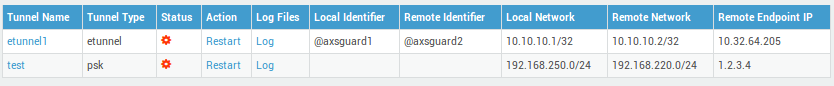
IPsec Status
-
Navigate to VPN > Status > IPsec.
-
Click on a tunnel ID to view its Phase 1 and Phase 2 status.
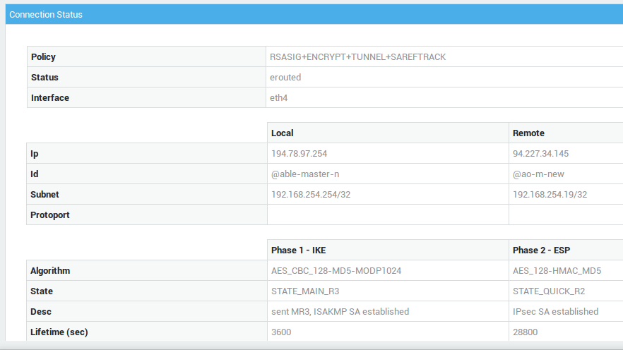
IPsec Status Colors |
Description |
|---|---|
Green |
The IPsec tunnel is up. |
Red |
Mistakes have been made in the IPsec configuration or the remote connection has been lost. |
Orange |
This status indicates that either:
|
Grey |
The IPsec / E-tunnel definition is error-free, but the tunnel is not enabled. |
Info
- Using the IPsec status facilitates troubleshooting, as it indicates which phase is failing.
- Click the tunnel log link to view the associated logs.
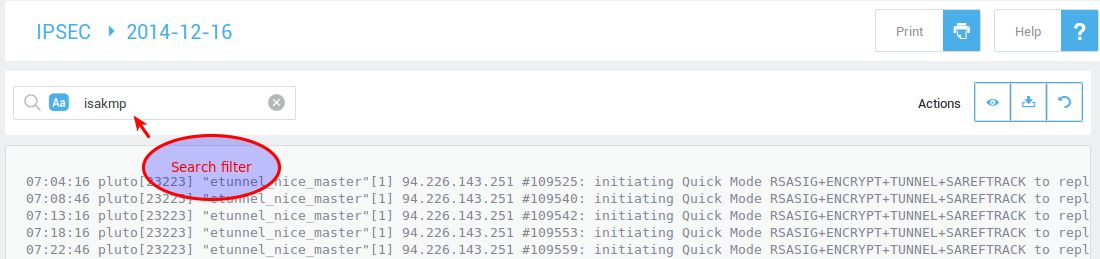
Summary Logs
The summary logs track IPsec tunnel up and down events, providing detailed metadata such as tunnel uptime, data transferred, and peer IP addresses.
-
Navigate to VPN > IPsec > Logs > Summary.
-
Click on the desired log date in the list.
-
Use a search filter to facilitate your search for particular log entries.

Detailed Logs
The detailed IPsec logs provide a wealth of information, including details about Phase 1 and Phase 2 negotiations, XAUTH authentication, connection duration, and even detection of inactive peers.
-
Navigate to VPN > IPsec > Logs > Detailed.
-
Click on the desired log date in the list.
-
Use a search filter to facilitate your search for particular log entries.
Configuration Examples
E-tunnel with RSA Authentication
Overview
In this section we explain how to set up an e-tunnel with RSA authentication between two AXS Guard appliances, based on the setup illustrated below. We start by configuring AXS Guard#1, followed by AXS Guard#2 (from left to right).

The most important considerations are:
-
To correctly mirror the local and remote phase 1 parameters on both IPsec endpoints.
-
To correctly mirror the local and remote phase 2 parameters on both IPsec endpoints.
Tunnel Setup
-
Log in to AXS Guard #1.
-
Navigate to VPN > IPsec > Tunnels.
-
Click on Add new.
-
Enter a name and description for the new tunnel.
-
Check the "e-tunnel" option.
-
Enter the phase 1 settings as shown in the screenshot below:
-
Enter the phase 2 settings as shown in the screenshot below:
-
Click on Save. An activation notice will be displayed.
-
Repeat the same steps on AXS Guard #2.
Important
The virtual endpoint IP addresses must be unique in their respective networks.
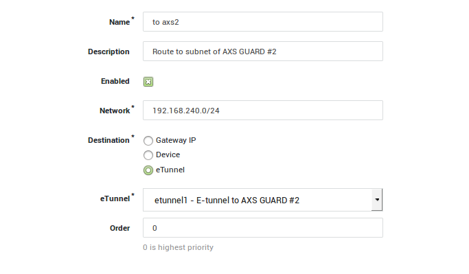
Routing
In this section, we explain how to add the necessary routing to each of the AXS Guard secure subnets. The appropriate routing entries must be added on each AXS Guard appliance:
AXS Guard #1
-
Log on to AXS Guard#1.
-
Go to Network > Routing.
-
Click on Add new.
-
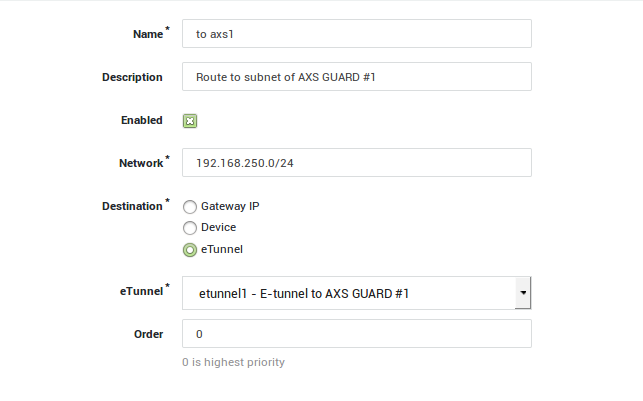
Add a route towards the AXS Guard#2 subnet as shown below.
-
Click on Save.
AXS Guard #2
-
Log on to AXS Guard#2.
-
Go to Network > Routing.
-
Click on Add new.
-
Add a route towards the AXS Guard#1 subnet as shown below.
-
Click on Save
Checking the Tunnel Status
-
Log on to the first AXS Guard appliance.
-
Navigate to VPN > IPsec > Status.
-
Restart the E-tunnel (if necessary) by clicking on Restart.
Checking the Firewall Configuration
Important
Firewall rules are automatically added when e-tunnel routing entries are created. However, they must be adjusted manually if the routing entries are modified.
-
Log on to AXS Guard#1.
-
Navigate to Firewall > Policies > Static
-
Click on the stat-vpn policy.
-
Repeat steps 1 to 3 for AXS Guard#2.
E-tunnel Star Network
Overview
In this section, we explain how to create a star network connecting three AXS Guard appliances via e-tunnels. The setup is illustrated below.
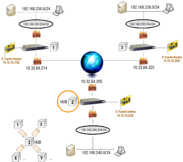
The most important considerations are:
-
The central AXS Guard (hub) has to be connected to all other AXS Guard appliances with an e-tunnel.
-
You must add the appropriate routing entries on all AXS Guard appliances to connect the subnets.
-
The needed firewall rules are generated automatically and should be adapted according to your needs. You should always check the static firewall policy of the central AXS Guard appliance (hub).
-
To avoid mistakes, only use 1 virtual IP address per AXS Guard.
-
Enable Dead Peer Detection if you connect to a site equipped with an AXS Guard failover system.
Tunnel Setup
AXS Guard #1: Connect AXS Guard#1 to AXS Guard#2 with an e-tunnel.
AXS Guard #2: Connect AXS Guard#2 to AXS Guard#1 with an e-tunnel, then configure an additional e-tunnel to connect to AXS Guard#3:
-
Log on to the AXS Guard#2.
-
Navigate to VPN > IPsec > Tunnels.
-
Click on the existing Tunnel.
-
Click on Edit as New.
-
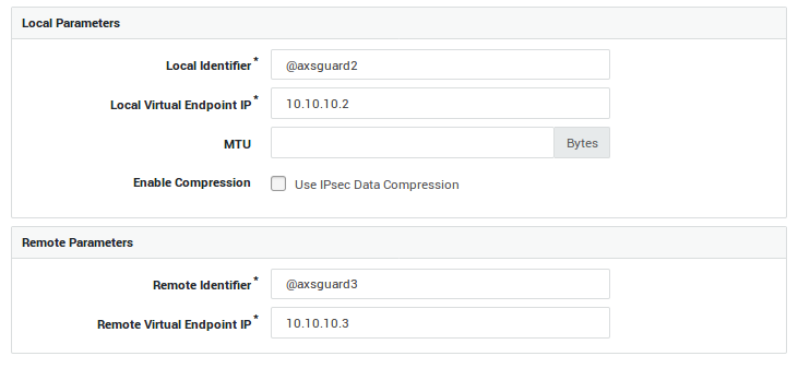
Use the same phase 1 settings as shown in the example below:
-
Update the phase 2 parameters as shown in the example below.
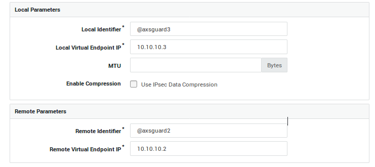
AXS Guard #3
-
Log on to AXS Guard#3.
-
Navigate to VPN > IPsec > Tunnels.
-
Click on Add new.
-
Follow the same steps as you did for AXS Guard#1 and AXS Guard#2, but modify the following:
- The remote endpoint IP address
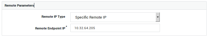
-
The local parameters
-
The remote parameters
Routing
The appropriate routing entries must be added on all AXS Guard appliances.
AXS Guard #1
-
Log on to AXS Guard#1.
-
Navigate to Network > Routing.
-
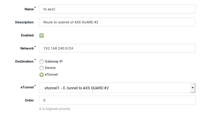
Click on Add new.
-
Enter the routing settings towards the AXS Guard#2 subnet as shown in the example below and save your configuration.
-
Enter the routing settings towards the AXS Guard#3 subnet and save your configuration.
AXS Guard #2
-
Log on to AXS Guard#2.
-
Navigate to Network > Routing.
-
Click on Add new.
-
Enter the routing settings towards the AXS Guard#1 subnet and save your configuration.
-
Enter the routing settings towards the AXS Guard#3 subnet and save your configuration.
AXS Guard #3
-
Log on to AXS Guard#3.
-
Navigate to Network > Routing.
-
Click on Add new.
-
Enter the routing settings towards the AXS Guard#2 subnet and save your configuration.
-
Enter the routing settings towards the AXS Guard#1 subnet and save your configuration.
Checking the Tunnel Status
If all settings are correct, the tunnel is started immediately.
-
Log on to the first AXS Guard appliance.
-
Navigate to VPN > IPsec > Status.
-
Restart the e-tunnel (if necessary) by clicking on Restart.
Checking the Firewall Configuration
Important
- Firewall rules are automatically added when e-tunnel routing entries are created. However, they must be manually adjusted if the routing entries are modified.
- Firewall rules that allow network traffic between the endpoints and the e-tunnel hub are added automatically.
- Firewall rules must be added manually on the AXS Guard e-tunnel hub to allow network traffic between all network endpoints.
AXS Guard #2
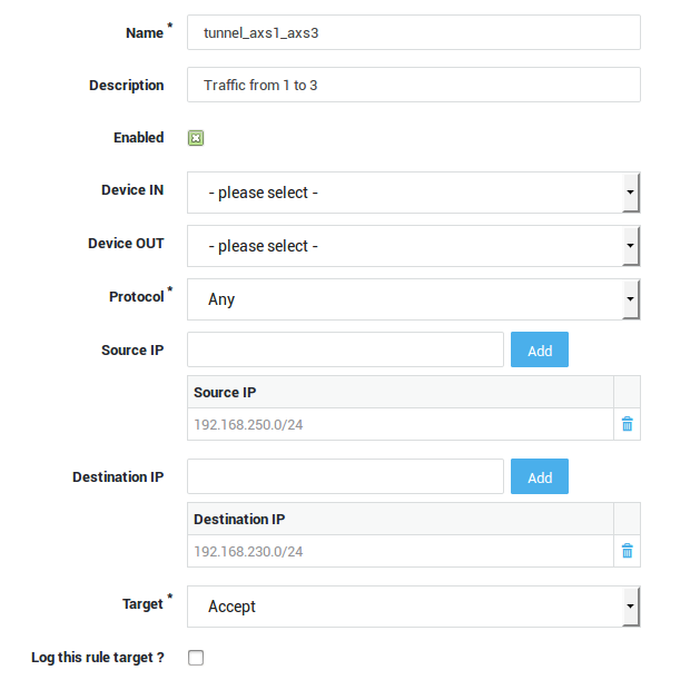
Create firewall rules to allow traffic between the AXS Guard#1 and AXS Guard#3 subnets:
-
Log on to AXS Guard#2.
-
Navigate to Firewall > Rules > Through.
-
Search for the firewall rules which were automatically created for both tunnel definitions, e.g. enter
tunnelin the search filter.
-
Open one of the newly created firewall rules.
-
Click on Edit as New.
-
Create a new firewall rule to allow network traffic from AXS Guard#1 subnet to AXS Guard#3 subnet and save.
-
Create a new firewall rule to allow network traffic from AXS Guard#3 subnet to AXS Guard#1 subnet and save.
Add the created Firewall Rules to the Static Firewall Policy stat-vpn:
-
Navigate to Firewall > Policies > Static.
-
Click on stat-vpn.
-
Add the previously created firewall rules to the
stat-vpnpolicy and update your configuration.
E-tunnel with Failover
Overview
In this section, we explain how to create an e-tunnel VPN failover setup. This setup is only possible when connecting an AXS Guard appliance to another AXS Guard appliance with two (or more) Internet lines. The example in this section is based on the illustration below.
Tunnel Setup
-
Log in to AXS Guard A.
-
Create an e-tunnel towards the primary public IP address of AXS Guard B.
-
Enable Dead Peer Detection.
-
Create another e-tunnel towards the secondary public IP address of AXS Guard B.
-
Enable Dead Peer Detection.

Important
- Use a unique Virtual IP address for each tunnel definition.
- Use a unique connection identifier for each tunnel definition.
- Dead Peer Detection must always be enabled for failover configurations.
AXS Guard B
-
Create an e-tunnel towards the public IP address of AXS Guard A.
-
Enable Dead Peer Detection.
-
Specify the Interface to bind IPsec (Internet Line 1).
-
Create a second e-tunnel towards the public IP address of AXS Guard A.
-
Enable Dead Peer Detection.
-
Specify the Interface to bind IPsec (Internet Line 2).
Important
- Use a unique Virtual IP address for each tunnel definition.
- Use a unique identifier for each tunnel definition.
- Dead Peer Detection must be enabled for the failover to function.
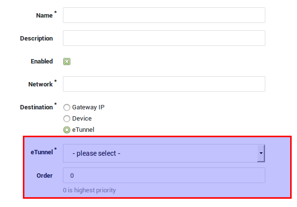
Routing
AXS Guard A
Add the required routes.
-
For the e-tunnel towards the first public IP address of AXS Guard B, use
priority 0. -
For the e-tunnel towards the secondary public IP address of AXS Guard B, use
priority 1.
AXS Guard B (with multiple Internet lines)
Add the required routing priorities.
-
For the 1st e-tunnel to AXS Guard A, use
priority 0. -
For the 2nd e-tunnel to AXS Guard A, use
priority 1.
Info
0 is the highest priority.
Checking the Tunnel Status
Follow the same steps as explained in Checking the Tunnel Status.
Checking the Firewall Configuration
Follow the same steps as explained in Checking the Firewall Configuration.
Important
Firewall rules are automatically added when e-tunnel routing entries are created. However, they must be adjusted manually if the routing entries are modified.
Troubleshooting
I cannot access the AXS GUARD IPsec menu.
-
Log on to the AXS Guard Administrator Tool as explained in the AXS Guard System Administration How To, which can be accessed by clicking on the permanently available Documentation button in the Administrator Tool.
-
Navigate to System > Feature Activation and select VPN.
-
Verify if the Do you use VPN IPsec? option is enabled.
My IPsec / E-tunnel is up and running, but I cannot access certain servers in the remote LAN.
-
Verify the routing on every IPsec endpoint. Routes for aliases should always be entered manually (see further).
-
Verify the Firewall settings on every IPsec endpoint.
-
Ensure that the servers you are trying to reach point to the correct gateway, so that server replies can be routed correctly and don’t get lost. Consult the documentation of your server(s) if necessary.
I cannot establish an IPsec tunnel between the AXS GUARD and a third-party device.
-
Only use encryption and authentication algorithms which are supported by both IPsec endpoints.
-
Verify the Phase 1 and Phase 2 parameters on each IPsec endpoint. They should match.
-
Make sure the Phase 2 local and remote parameters are crossed on both IPsec endpoints.
-
Verify the routing on every IPsec endpoint.
-
Verify the Firewall settings on every IPsec endpoint.
-
Check the advanced IPsec settings, e.g. the MTU, on every IPsec endpoint.
-
Verify if the third-party device accepts ESP packets. Forcing NAT-Traversal is sometimes necessary even when the peers are not NAT-ted (e.g. when a router is not forwarding the ESP packets).
I cannot reach a certain LAN segment in an E-tunnel Star Network.
-
Verify the routing entries on the concerned AXS Guard appliances. Routes for aliases should always be entered manually.
-
Verify the Firewall settings on the concerned AXS Guard appliances.
-
Make sure the central AXS Guard (hub) Firewall allows traffic between all subnets.
Failover does not work
-
Navigate to VPN > IPsec > Tunnels.
-
Click on the appropriate E-tunnel name.
-
On the bottom of the screen, expand the Advanced IPsec Options.
-
Ensure Dead Peer Detection is enabled.
How do I specify multiple allowed protocols and ports for a tunnel?
-
It is possible to limit IPsec traffic to certain protocols and ports. It is not possible to enter a list of allowed protocols and ports. You can only add a single protocol / port combination to each tunnel definition.
-
A workaround is to replicate the tunnel definition (Edit as new) and add the desired allowed protocol / port combination. Save the replicated tunnel definition under a new name. Repeat the procedure as many times as needed.
Routing via etunnel: Firewall Rules are not automatically added for aliases.
When adding a route via an e-tunnel, Firewall Rules for the subnets are added automatically. However, routes for any alias on a secure device should always be added manually.
Example:
Configuration of eth0: 172.16.32.203/24 with alias 172.16.202.254/24
Adding a route for the destination network 172.16.200.0/24 via an E-tunnel automatically adds the the following Firewall Rules:
-
r1
On any ACCEPT 172.16.32.0/24 > 172.16.200.0/24 -
r2
On any ACCEPT 172.16.200.0/24 > 172.16.32.0/24
This means that network traffic originating from 172.16.202.0/24
cannot be sent to 172.16.200.0/24. The Firewall Rules should be
entered manually.
More information about routing is available in the AXS Guard System Administration How To, which can be accessed by clicking on the permanently available Documentation button in the Administrator Tool.
Issues with NAT-Traversal
Important
Do not use the endpoint IP as a connection identifier on an appliance of which the Internet interface(s) is/are NATted. The responding appliance checks if the connection identifier matches the source IP address of the appliance that initiates the connection. If the initiating appliance is NATted, the responder will see the translated IP address, which is of course different from the actual source IP. As a result, the responder will refuse the connection and an authentication failure will appear in its IPsec server log.
In the following log, you can see that the identifier is 10.132.23.135 (NATted IP), while the actual IP of the initiating appliance is 10.132.23.136. Since there is a mismatch, the responder refuses to authenticate the initiator.
0:48:43 pluto[30792] "psk_to136" #4: Main mode peer ID is ID_IPV4_ADDR: '10.132.23.135'
10:48:43 pluto[30792] "psk_to136" #4: no suitable connection for peer '10.132.23.135'
10:48:43 pluto[30792] "psk_to136" #4: sending encrypted notification INVALID_ID_INFORMATION to 10.132.23.136:500
10:48:50 pluto[30792] "psk_to136" #3: discarding duplicate packet; already STATE_MAIN_I3
10:48:50 pluto[30792] "psk_to136" #3: ignoring informational payload, type INVALID_ID_INFORMATION msgid=00000000
10:48:50 pluto[30792] "psk_to136" #3: received and ignored informational message
10:48:53 pluto[30792] "psk_to136" #4: Main mode peer ID is ID_IPV4_ADDR: '10.132.23.135'
10:48:53 pluto[30792] "psk_to136" #4: no suitable connection for peer '10.132.23.135'
10:48:53 pluto[30792] "psk_to136" #4: sending encrypted notification INVALID_ID_INFORMATION to 10.132.23.136:500
10:49:13 pluto[30792] "psk_to136" #4: Main mode peer ID is ID_IPV4_ADDR: '10.132.23.135'
10:49:13 pluto[30792] "psk_to136" #4: no suitable connection for peer '10.132.23.135'
10:49:13 pluto[30792] "psk_to136" #4: sending encrypted notification INVALID_ID_INFORMATION to 10.132.23.136:500
10:49:30 pluto[30792] "psk_to136" #3: max number of retransmissions (2) reached STATE_MAIN_I3.  Possible authentication failure: no acceptable response to our first encrypted message
10:49:30 pluto[30792] "psk_to136" #3: starting keying attempt 2 of an unlimited number
10:49:30 pluto[30792] "psk_to136" #5: initiating Main Mode to replace #3
I’m getting the following message: "A problem occurred while fetching the public RSA key. Please contact support."
As soon as you enable the IPsec feature, the AXS Guard will start to generate the RSA keys required for authentication. This process may take a while, especially on virtual appliances. Please be patient.
Support
If you encounter a problem
If you encounter a problem with AXS Guard, follow the steps below:
-
Check the troubleshooting section of the feature-specific manual.
-
Check the knowledge base on this site for information about special configurations.
-
If no solution is available in any of the above sources, contact your AXS Guard vendor.
Contact Information
(+32) 15-504-400
support@axsguard.com