System Administration Guide
Introduction
About this Document
This document serves as a reference source for technical personnel and system administrators who are responsible for licensing and configuring AXS Guard appliances. Explanations of various concepts, e.g. AXS Guard users and groups, are provided together with instructions on how to configure their relevant settings.
Topics covered in this document:
- How to access the AXS Guard web-based administrator tool
- How to configure your appliance using the various configuration wizards
- Creating a user with administrative privileges
- Licensing your appliance
- Quick navigation reference
- How to use the AXS Guard system menu
- Activating software options
- System backup and restore
- Software updates
- Server-Side SSL and TLS options
- Security levels and policies
- User and group management
- Computer management
- Network configuration (Network devices, VLANs, DNS, DHCP, Routing, NAT, etc.)
- NTP
- System health & status
- Reporting & GDPR
- System logging
- Introduction to authentication settings
- SNMP
Examples used in this Guide
All setups and configuration examples in this guide are executed as an advanced administrator. Some options are not available if you log in as a full administrator or a user with lower access privileges.
As software development and documentation are ongoing processes, the screenshots shown in this guide may slightly deviate from the current user interface.
Accessing the Administrator Tool
Overview
The administrator tool serves as a web-based interface for configuring your AXS Guard appliance.
After connecting the appliance to your network, you can conveniently access its administrator tool using a standard web browser from any workstation within its network. All connections are secure (HTTPS) and necessitate acceptance of the AXS Guard self-signed certificate.
Refer to the Getting Started guide for instructions on connecting the AXS Guard appliance to your network.
System Default IP Address
| AXS Guard Used as a Proxy Server? | Address to navigate to: |
|---|---|
| Not used as a Proxy Server | https://LAN_IP_address:82, e.g. https://192.168.250.254:82 (AXS Guard system default LAN IP address) |
| Used as a Proxy Server | Set the secure LAN IP address of your AXS Guard appliance as the browser's proxy, and use port number 3128. To access the login page, simply enter tool in the URL field of your web browser.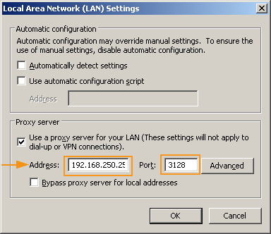 |
Proxy settings
- If the connection fails, check your browser’s proxy settings. Remove any previous settings and try again.
- If Single Sign-On (SSO) is used, the browser’s proxy settings are set automatically. For more information, please refer to the document, AXS Guard Single Sign-On How To, available through the permanently on-screen Documentation button in the Administrator Tool.
- For more information on using the AXS Guard Proxy server, please refer to the document, AXS Guard Web Access How To, available through the permanently onscreen Documentation button in the Administrator Tool.
Logging in to the Administrator Tool
Supported Browsers
| Browser | Version |
|---|---|
| Google Chrome | Current versions only |
| Microsoft Edge | Current versions only |
| Mozilla Firefox | Current versions only |
| Safari | Current versions only |
| Opera | Current versions only |
Login Procedure
To log in to the AXS Guard web-based administrator tool, you need a web browser (see the list of supported browsers). The web-based administrator tool listens on TCP port 82. If you can’t access the login page, verify your browser’s proxy settings.
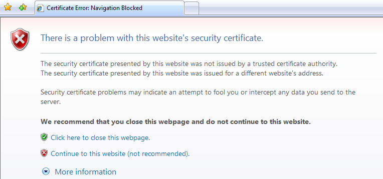
Access is secured by SSL encryption over the HTTP protocol. The AXS Guard appliance is secured with a self-signed certificate, which means the browser will show a warning asking you to accept the certificate (also see the image below).
The procedure for accepting self-signed certificates varies between browsers. After accepting the certificate, the login screen will appear.
-
Start your favorite Internet browser.
-
Enter the default URL for the Administrator Tool, i.e. https://192.168.250.254:82
-
Accept the self-signed certificate before you continue. After the certificate has been accepted, the AXS Guard login screen will appear.
Important
- Include the port number after the IP address or the connection will fail.
- If the AXS Guard is configured as the browser’s proxy, your may enter
toolas the URL instead of the appliance’s default IP address and port number.
-
Enter the default system administrator’s username (
sysadmin) and password (sysadmin).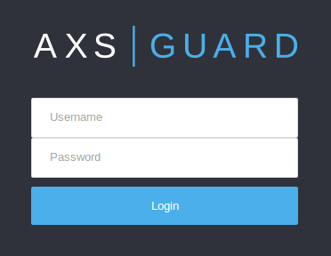
-
Press enter or click on the login button to proceed.
-
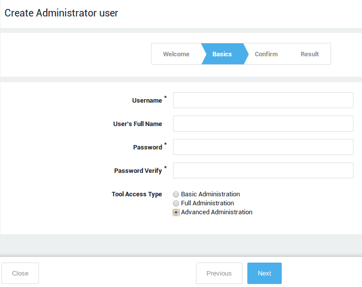
Complete the first wizard to create a user with full or advanced administrative privileges. This is required to license and further configure your appliance.
sysadmin Access Rights
Important
Changing the factory default sysadmin password is critical for security. It should be changed ASAP to prevent non-authorized users from accessing the AXS Guard administrator tool.
The sysadmin user allows you to:
- Create and modify new AXS Guard users, including system administrators.
- Assign access privileges to new AXS Guard users.
- Change the sysadmin password.
To license your appliance and configure other features, you must log in as an advanced administrator.
Configuration Wizards
Overview
The configuration wizards walk you through the essential configuration steps to get your system up and running in no time. Each wizard must be completed before the next one becomes available. In this section, we explain the following wizards:
-
Setup wizard: Includes creating a new administrator, configuring initial system settings and network devices.
-
Licensing wizard: During this stage, you will be invited to enter your customer information and upload your system license to get your appliance to full operational, in-service status.
-
Group and user wizard: Allows you to easily create new users and groups and also to synchronize users and groups from your Directory Server (if applicable).
Click on the Help button if you need assistance.
Starting the Wizards
-
Log in to the AXS Guard.
-
If you are logging in for the first time, the wizards will start automatically. Otherwise, click on Wizards.
-
Follow the on-screen instructions.
Important
Do not skip any wizards. Start from the top one and work your way down the list.
Basic System Configuration
Creating a new System Administrator
Follow the on-screen instructions to create a new system administrator with full or advanced privileges (required to license your appliance). Fields with descriptions in bold are required, other fields are optional. Click on help for assistance.
System Setup
Follow the on-screen instructions to set up your system.
Change the default sysadmin password to prevent unauthorized access to the appliance. Use a secure, complex password.
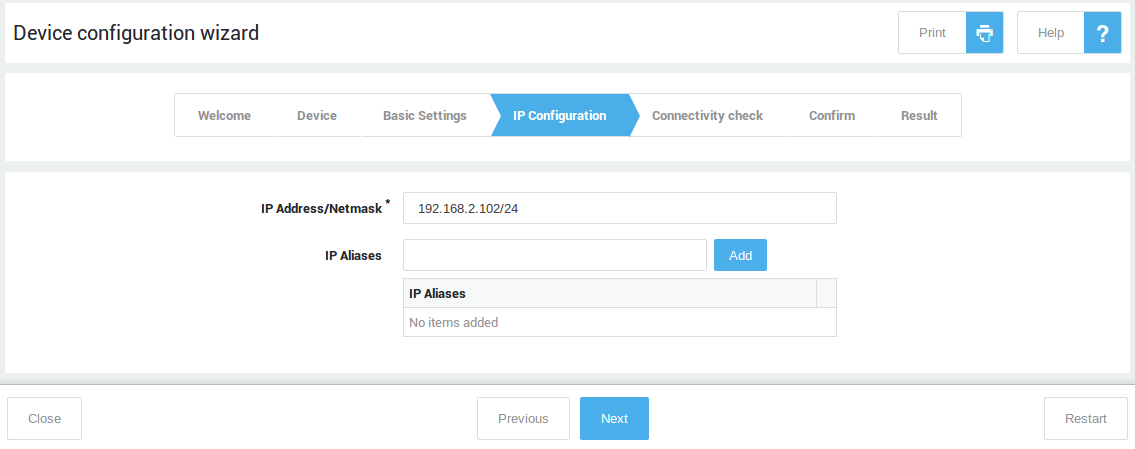
Setting up your Network Devices
Follow the on-screen instructions to set up your network devices.
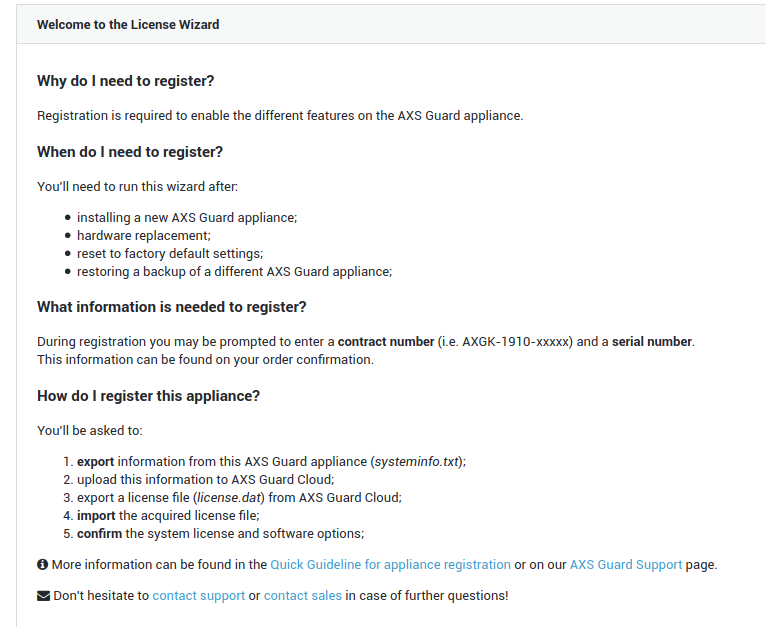
License Wizard
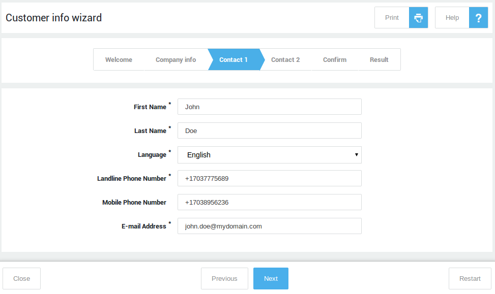
Customer Information
Follow the on-screen instructions to enter your customer information.
Licensing your Appliance
Follow the on-screen instructions to license your appliance.
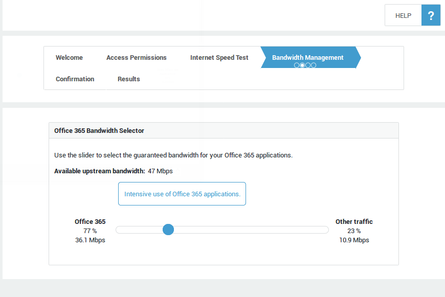
Microsoft Cloud
The Office 365 FAST Lane wizard will help you to securely connect your network with the Microsoft Office 365 cloud and will allow you to configure the optimal bandwidth settings and redundant connections for your Office 365 applications and services.
An Internet speed test will be executed to calculate the optimal bandwidth settings. Please note that users will be temporarily disconnected from the Internet for the duration of the speed test. Their connection will be restored after completion of the test.
Groups and Users
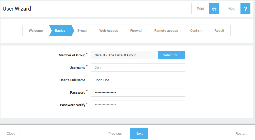
Creating Users
Follow the on-screen instructions to create new users.
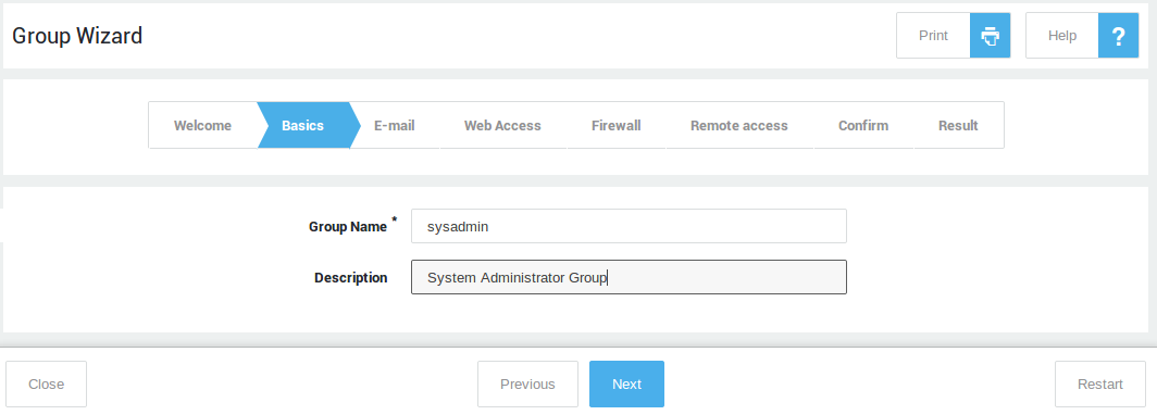
Creating Groups
Follow the on-screen instructions to create new groups.
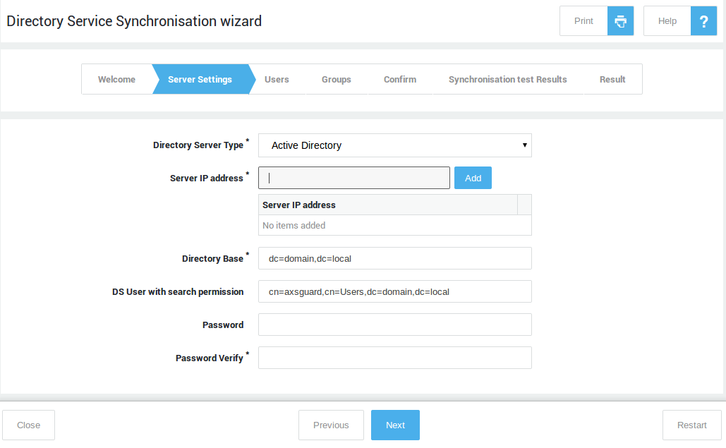
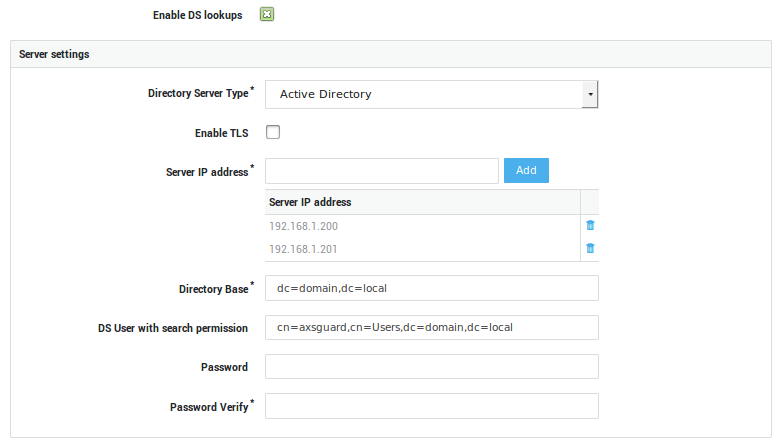
Synchronizing your Directory Server
Follow the on-screen instructions to import and synchronize the users and groups from your Directory Server (LDAP sync).
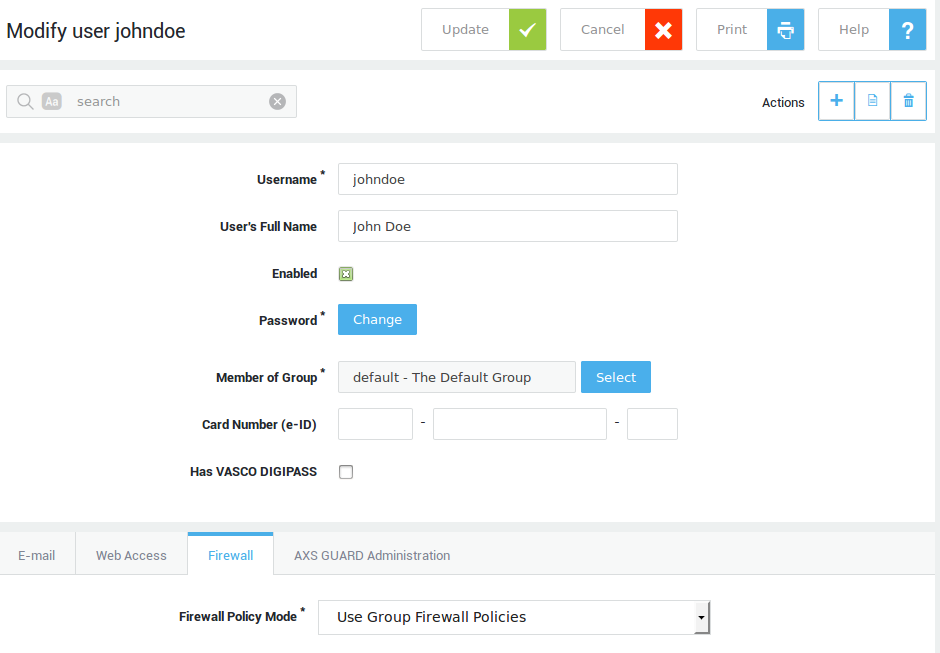
Creating a User with Administrative Privileges
Change the factory default sysadmin password to prevent unauthorized access to the appliance.
With the sysadmin user, you can create new user accounts, including accounts with administrative privileges. However, it won’t allow you to configure and manage your appliance. To further configure and manage your appliance, you must create a new user with full or advanced administrative privileges. This also facilitates troubleshooting and monitoring, since all actions performed by administrators are logged by username (under System > Logs > Admin Tool).
-
Log in to the AXS Guard.
-
Navigate to Users & Groups > Users.
-
Click on the
+sign to add a new user.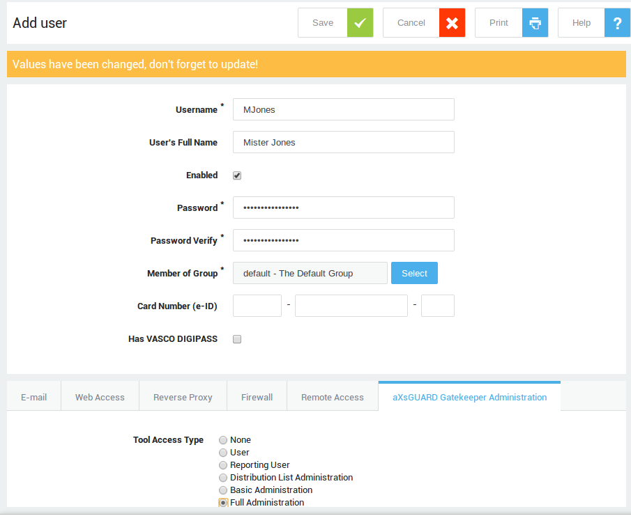
-
Enter a username.
-
Enter the user’s full name (optional).
-
Enter and confirm the user’s password. Make sure to use a secure, complex password.
-
Under the AXS Guard Administration tab, select Full Administration.
-
Click on Update / Save.
-
Log off and log in with the newly created administrator account. Use this account to further configure your appliance.
Licensing your Appliance
About
Licensing is the process of registering an AXS Guard appliance to generate a license file, enabling the appliance to operate in accordance with the purchased software bundle and SLA. After installation and before licensing, the administrator tool is accessible for configuration and management; however, core services such as authentication remain unavailable until the appliance is properly licensed.
First-time licensing
Overview
Licensing your AXS Guard appliance requires three steps:
-
Downloading a
systeminfo.txtfile from your appliance. This file contains information specific to your appliance, including:-
A unique host key
-
A configuration key, which is specific to the configuration of your appliance and which may change when:
-
the appliance is reset to factory default settings, or
-
under certain conditions when a backup is restored (see restoring a backup from another appliance)
-
-
-
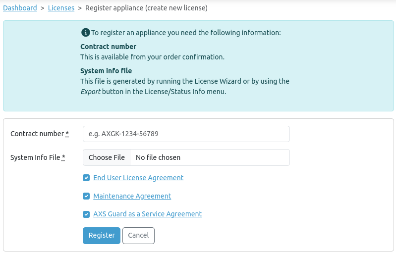
Acquiring a license file via the Cyber Resilience Portal, using the:
-
systeminfo.txtfile -
Contract number as found in your AXS Guard order confirmation
-
Details of your organization
-
-
Uploading the
license.datfile to your AXS Guard appliance.
After licensing your appliance, log in as the sysadmin user to create a new user with advanced administrative privileges. This step is necessary to enable the configuration of all AXS Guard features.
Downloading a System Info file
-
Log in to the AXS Guard appliance.
-
Navigate to System > Status > System Info.
-
Click on the Export button to download
systeminfo.txtfile.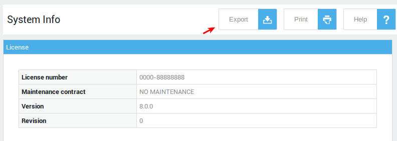
Acquiring a License file
To obtain a license file for your AXS Guard appliance, upload the system info file to the Cyber Resilience Portal and follow the on-screen instructions. The systeminfo.txt file is used to identify your appliance before issuing the license file.
Types of Licenses
- Commercial license: remains valid until the expiration of your contract and is restricted to the purchased software bundle and SLA.
- Evaluation license: allows you to test and evaluate the appliance with all features enabled for a period of 30 days.
Uploading your License File
-
Log in to your AXS Guard appliance.
-
Navigate to System > Licence > Import.
-
Select your
license.datfile and click on update to upload it to your appliance.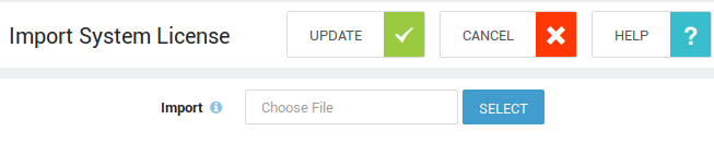
Important
After licensing your appliance, the factory default sysadmin user will be restricted to the creation and modification of user accounts. Create a new account with advanced administrative privileges to further configure your appliance.
Viewing License information
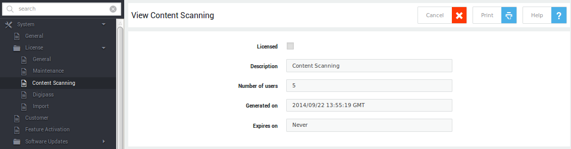
After licensing your appliance, new items are made available under System > License:
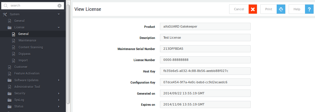
General
Contains essential license information, retrieved from the license.dat file.
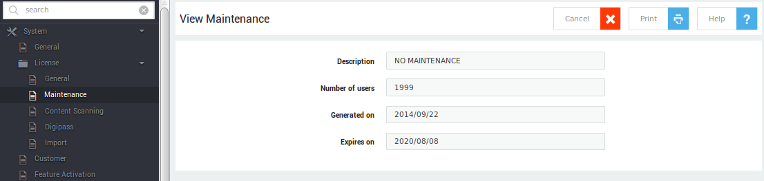
Maintenance
Provides information about your SLA. When your contract is about to expire, a status message will appear here.
Protection Pack
Provides information about your protection pack (Essential, Comfort or Premium).
Authenticators
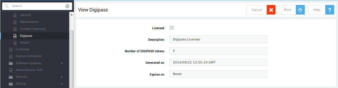
Provides information about the OATH and DIGIPASS tokens included in your license.
Relicensing
Guidelines
Relicensing is necessary under the following circumstances:
- After restoring an AXS Guard appliance to factory default settings without restoring a backup.
- After restoring a backup from another AXS Guard appliance (e.g., to a spare unit).
- When upgrading from an evaluation license to a commercial license.
Important
Buying new software options or changing the contract does not require relicensing. The AXS Guard appliance automatically contacts the back office to retrieve the updated license information. Please note that new software options must be activated before they can be used.
For canceled software options or maintenance contracts, a status message with a confirmation link is automatically generated. If the cancellation remains unconfirmed, the options are terminated after a 30-day grace period.
Factory default without restoring a backup
Restoring an appliance to the factory default state resets the system and changes the configuration key. In this situation, the running license remains bound to the previous configuration key, making relicensing impossible.
The system administrator must contact support@axsguard.com to release the license. Once released, relicensing follows the same procedure as first-time licensing.
Restoring a backup from another appliance
Restoring a backup created by the same appliance does not require relicensing because the host key and configuration key remain unchanged and match those supplied in the original system information file used for licensing.
However, restoring a backup from a different appliance (e.g., restoring a backup to a spare unit) requires relicensing, as the host key differs from the one in the original system information file. After the backup is restored, a 30-day grace period begins. During this period, all services remain available. After the grace period ends, all services stop, although the administrator tool remains accessible for minimal configuration and management.
The grace period allows system administrators to contact support@axsguard.com to release the appliance from its original license and proceed with relicensing. Relicensing follows the same procedure as first-time licensing.
Upgrading from an Evaluation to a Commercial License
With an evaluation license, a 30-day grace period is imposed during which all services remain available. After this period, all services stop, but the administrator tool remains accessible for minimal configuration and management. System administrators must relicense with a commercial license before the evaluation license expires. Please contact our sales department to transition from an evaluation license to a commercial license.
Relicensing follows the same procedure as first-time licensing.
Quick Navigation Reference
Overview
The Administrator Tool interface has three panes (numbered in the image below): the top pane is static; the left pane allows you to access the menus of the features that are enabled on your appliance. The right pane displays the configuration settings of the selected menu for viewing and modifying. The functionality offered in each pane is explained in the following sections. A search function is available for quick and easy access to menu items.
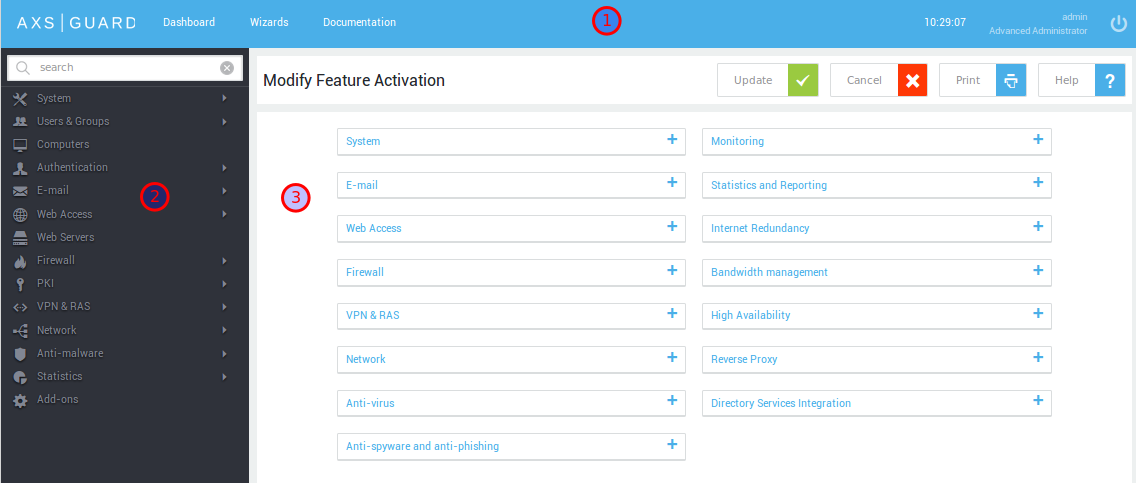
System Information and Permanently On-Screen Buttons
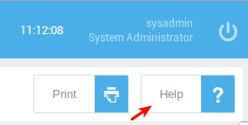
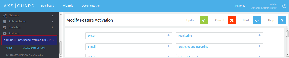
The system information (version number, revision number, etc.) is permanently visible in the left pane. The standard Dashboard, Wizards, Documentation and the Logout button are located in the top pane. The functionality provided by these buttons is described in the table below.
| Info / Button | Description |
|---|---|
| Version / Revision (left pane) | AXS Guard version and revision numbers (important for troubleshooting and support). |
| Dashboard | Shows vital information about your system’s health, e.g. configuration warnings, the system load, the uptime, etc. |
| Wizards | Provides access to the various configuration wizards. |
| Documentation | Provides access to all available documentation (HTML and PDF format). |
| System Time | Shows the AXS Guard system time, which is important for time-sensitive processes such as DIGIPASS authentication. |
| Administrator Name and Level | The username and the corresponding access level of the person who is logged in to the administrator tool. |
| Logout | Logs the user out of the AXS Guard. |
Menus and Submenus
The AXS Guard administrator tool has a treelike menu structure. Selecting a menu or submenu item will show the corresponding configuration in the right pane.
Some menu items, such as Computers, don’t have submenus. Feature-specific submenu items are explained separately in the AXS Guard documentation.
| Main Menu Item | Description |
|---|---|
| System | This menu displays several system-critical tools, system settings and system logs. Examples are: the AXS Guard Feature Activation tool, the AXS Guard DNS name, Domain name, System Update Settings, System Backup and Restore functions, and System Status, etc. |
| Users and Groups | This menu displays AXS Guard user and group settings for viewing or modification, e.g. Web access rights, firewall rights, etc. |
| Computers | This menu displays computer-specific settings for viewing or modification, e.g. firewall rights assigned to a specific server in the network. |
| Authentication | This menu displays authentication-related settings for viewing or modification. All available authentication methods, such as two-factor authentication (DIGIPASS), RADIUS authentication and other authentication methods are configured through this menu. |
| Feature-related | Feature-specific sub menus are available if the features have been activated. Examples are: advanced mail filtering, VPN solutions, HTTP Proxy and Reverse Proxy, Intrusion Prevention (IPS), Firewall, Directory Services, Bandwidth Management (QoS), Advanced Monitoring and Reporting, etc. |
| Sub Menu Item | Description |
|---|---|
| General | Main configuration settings for a feature can be viewed or modified in the General sub menu. Special syntax may be required for some features, e.g. the Directory Services feature requires LDAP syntax. Feature-specific settings and syntax are explained in the respective AXS Guard How To guides, available through the permanently on-screen Documentation button. |
| Status | This sub menu displays the feature-specific status information (see note below). This is useful if a problem occurs, for example a synchronization error with a Directory Server. The format of the status information is also feature-specific, and is explained in the respective AXS Guard How To guides, available through the permanently on-screen Documentation button. |
| Tools | Tools may be feature-specific or system-specific. The Tools sub menu allows new setups to be tested, and the system to be shut down for maintenance, etc. |
| Logs | Logs are records of system or feature-specific events, which help administrators to track and solve problems. Filters support searching for specific records within a given log file. |
Tables and Configuration Screens
When clicking on a menu or submenu, the corresponding configuration screen is shown in the right pane. Information or settings are presented in one of two ways:
-
Table form: tables provide an overview of settings for a particular type of object, e.g. groups, users, or uploaded DIGIPASS tokens.
-
Configuration screens: configuration screens show the settings of a particular feature for viewing or modification.
Settings can only be added or modified if an administrator is logged in with the appropriate rights.
Table View
Clicking on Users & Groups > Users displays the corresponding table in the right pane.
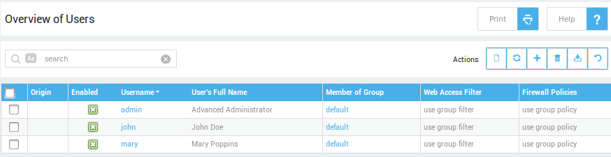
Deleted objects (e.g. a user, a configuration setting, etc.) cannot be recovered. For example, deleting a user irrevocably deletes the user’s mailbox and settings!
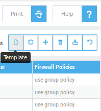
Two groups of controls are displayed on screen above the table: the search filter (explained below) and buttons for various operations: Items per page, Template, Add New, Delete, Export and Refresh. Hovering over a button will show its corresponding function.
| Button | Functionality |
|---|---|
| Add New | Adds a new (sub)menu-specific object, e.g. a user, a group, a client, a firewall rule, etc. |
| Delete | Deletes a (sub)menu-specific object, e.g. a user, a group, a client, a firewall policy, etc. Deleting an object with references is not allowed and generates a warning message. |
| Export | Exports the configuration data (e.g. User records) to a CSV file (Comma Separated Values). |
| Refresh | Refreshes the screen with the most current information. This is useful for checking that recent modifications have been applied (e.g. when synchronizing users and groups with a Directory Server). |
| Column Toggle | Inverts the selections in a column of records. |
| Row Toggle (top) | Enables/disables the record in a selected row. |
| Items per Page | This drop-down menu allows you to select the number of objects (e.g. users, groups, log files etc.) to be displayed on screen. |
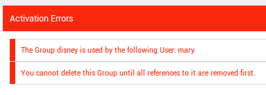
If you try to delete an object that is in use by another object, for example a group that still has members, an activation error will be shown (to preserve referential integrity).
Search Filters
Certain tables or files may contain a large numbers of records or entries, e.g. the full event logs. Search filters help administrators to restrict viewing specifically to relevant records and entries.
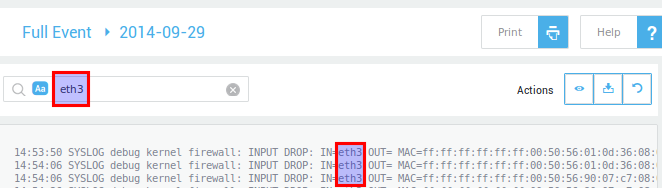
Search strings are case-sensitive by default. Press Aa to change the default behavior.
Configuration Screens
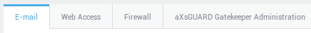
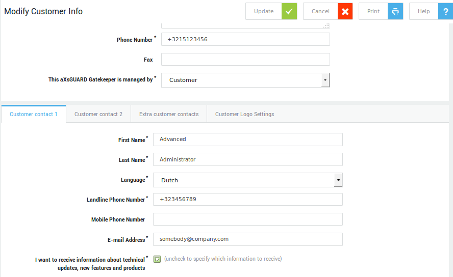
Click on an object in a table, e.g. a username, to show its corresponding configuration. Multiple settings may be grouped and accessible through separate tabs (as shown in the image below). Whether a tab is visible or not depends on the features that are activated on your appliance.
Configuration Settings
Some settings can be selected from drop-down lists, while some need to be entered manually in data fields using dedicated syntax. Some simply require a checkbox to be selected (examples are shown in the image below).
Required fields have a description in bold.
Configuration Screen Buttons
The various buttons are explained in the table below .
Hovering over a button will show its corresponding function.
| Button | Functionality |
|---|---|
| Add New | Adds a new (sub)menu-specific object, e.g. a user, a group, a client, a firewall rule, etc. |
| Cancel | Prevents new or modified settings from being stored and cancels the current operation, returning to the previous screen. |
| Delete | Deletes a (sub)menu-specific object, e.g. a user, a group, a client, a firewall policy, etc. Deleting an object with references is not allowed and generates a warning message. |
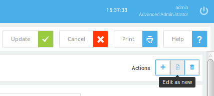
| Edit as New | Creates a copy of the selected record, keeping the same configuration options (for easy editing of a new record). |
| Save | Stores any new objects, e.g. a new firewall rule. The save button is only available where saving is required, otherwise the update button is shown. |
| Update | Submits any modifications to existing AXS Guard settings. Modifications are lost if not updated. |
| Prints the current screen. Useful for printing logs and statistics. | |
| Help | Displays help for the current screen. |
Manual System Configuration
Overview
This section covers the AXS Guard’s System menu, explaining configuration in detail for the following sub menus:
-
General
-
Customer
-
Feature Activation
-
UPS
-
Administrator Tool
-
Tools
General Menu
The Domain Name set on the System > General screen is not necessarily the Windows Domain Name. Please see the table below for more information.
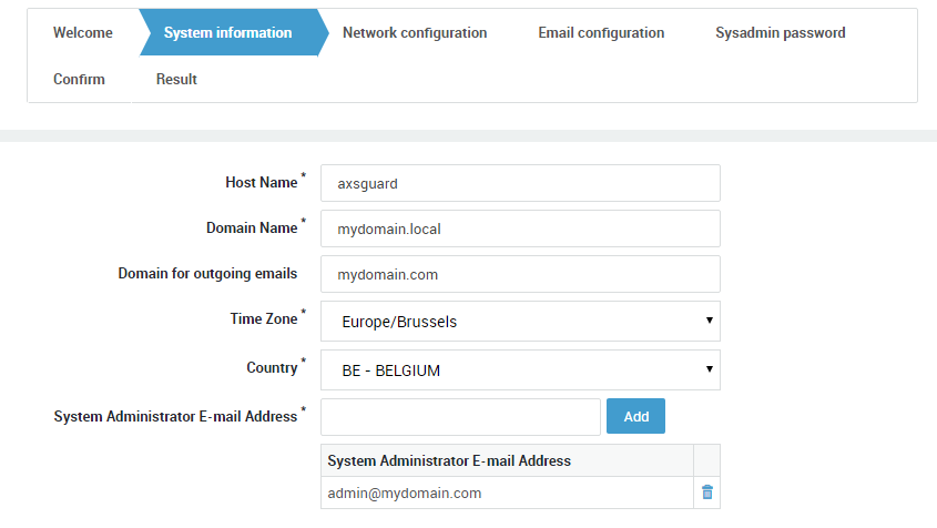
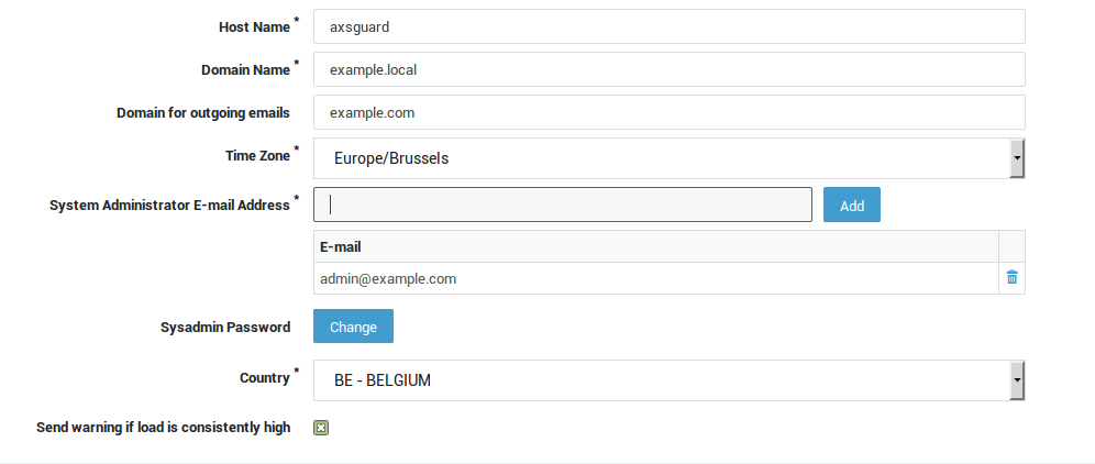
Navigate to System > General. A screen similar to the image below is displayed. Fields and their settings are explained in the table below .
| Field | Description |
|---|---|
| Host name | The hostname of the appliance. This name is used by the appliance’s own internal DNS server. axsguard is the system default. Do not change unless necessary. Changing the hostname requires advanced administrator access. |
| Domain Name | The name of your primary domain, e.g. example.com. This domain is used by the appliance’s internal DNS server and is also used when it sends an e-mail notification to system administrators or the outside world. |
| Domain for outgoing emails | Enter a domain with a valid MX record. This is only required if the domain name specified above is a local domain which is not resolvable on the Internet, e.g. example.local. |
| Time Zone | Select the appropriate time zone from the drop-down list. A correct system time is critical for time-sensitive processes such as Kerberos and DIGIPASS authentication. |
| System Administrator Email address | Enter the system administrator’s e-mail address. All reports generated by your appliance are sent to this e-mail address. Multiple e-mail addresses can be specified. |
| System Administrator Password | The factory default sysadmin password. It is highly recommended to change this password as soon as you install your appliance. |
| Country | Select the appropriate country from the drop-down list. |
| Send warning if load is consistently high | The appliance will automatically send an e-mail to system administrators if it detects a high system load during 5 consecutive days. The e-mail is sent to the e-mail address(es) specified under System > General. A high load average may be an indication of a task monopolizing a lot of CPU time, in which case you may want to upgrade your hardware. |
Customer Information
Use this screen to enter customer information, which is then uploaded to the Able customer database. Keeping this information up-to-date optimizes and facilitates Able customer support. Navigate to System > Customer to access a screen similar to the one shown below.
Feature Activation Menu
Additional software options can be purchased and enabled as required. The procedure to activate new software options is explained below.
Disabling unused features and options improves system performance.
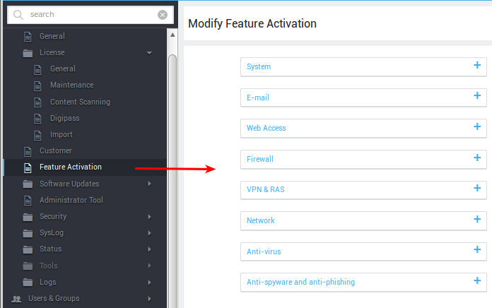
-
Log in to the appliance and navigate to System > Feature Activation.
-
Select the appropriate feature group, e.g.
Web Access. -
Use the slider buttons to activate or disable features, then update your configuration.
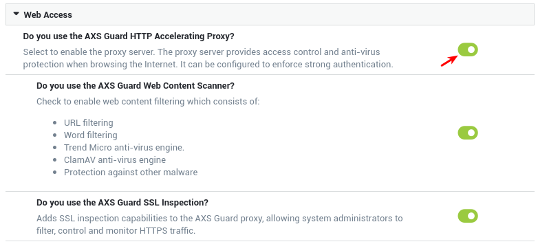
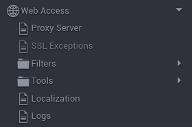
After activating a feature, its configuration menu and associated options automatically become available in the left pane:
UPS Settings
A UPS (uninterruptible power supply) is a device which allows a server to operate when its primary power source is lost. It also provides protection against power surges and potential data loss caused by ungraceful shutdowns.
UPS Monitoring over the Network
A commonly adopted solution among UPS vendors is the Simple Network Management Protocol (SNMP) card, which allows system administrators to manage multiple UPS devices remotely via a single platform.
The SNMP card of the UPS is connected to AXS Guard via a standard network port (RJ-45). It is recommended to use a UPS model with SNMP support, as it greatly simplifies the monitoring of the device and the system as a whole.
Local UPS Monitoring
Another method to gain access to the parameters of a UPS unit is to use outdated COM interfaces.
In this case, the UPS must be connected to AXS Guard with a proprietary serial cable and is usually monitored and configured through proprietary software.
Local UPS monitoring is deprecated
- There are no uniform standards and protocols for the data exchange.
- The UPS software usually has some restrictions.
- Using non-proprietary serial cables can cause the UPS to act in unwanted ways or malfunction.
- The most significant drawback is the inability to perform monitoring remotely via the network.
UPS Configuration
Go to System > Feature Activation > System to check whether the UPS feature is activated.

To configure your UPS settings:
-
Navigate to System > UPS.
-
Enter the correct settings for your UPS.
-
Update your configuration.
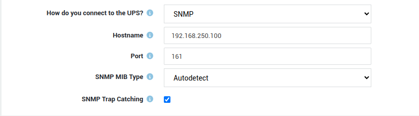
SNMP Settings
| Field | Description |
|---|---|
| Hostname | Enter the hostname or IP address of your UPS unit. |
| Port | The port number of the SNMP agent that is running on the UPS. Typically, SNMP agents listen on UDP port 161. |
| SNMP MIB Type | Select the MIB type that is compatible with your UPS. |
| SNMP Trap Catching | If enabled, the AXS Guard appliance will monitor its SNMP trap port and will re-poll the UPS whenever a trap is received. This happens, for example, when the UPS switches its battery on or off. In order for this feature to work, you must configure your UPS to deliver traps to the AXS Guard appliance. This is generally done by connecting to your SNMP card via a web browser or a telnet connection. You will need to configure the AXS Guard appliance as a trap receiver and make sure trap delivery is enabled. The AXS Guard appliance will fall back to polling behavior if it is unable to open its trap port, i.e. UDP 162 or if SNMP Trap Catching is disabled. |
Serial Port Settings
Local UPS monitoring is deprecated
It is recommended to use a UPS model with SNMP support, as it greatly simplifies the monitoring of the device and the system as a whole.
| Field | Description |
|---|---|
| UPS Type | Select the make and model of your UPS device. |
| UPS Cable Type | Select the cable type from the drop-down menu. Use the correct serial cable. Using non-proprietary serial cables can cause the UPS unit to act in unwanted ways or malfunction. |
| PSTN Device | The PSTN device as configured under Network > Devices > PSTN. This is required to establish serial communications with the UPS unit. |
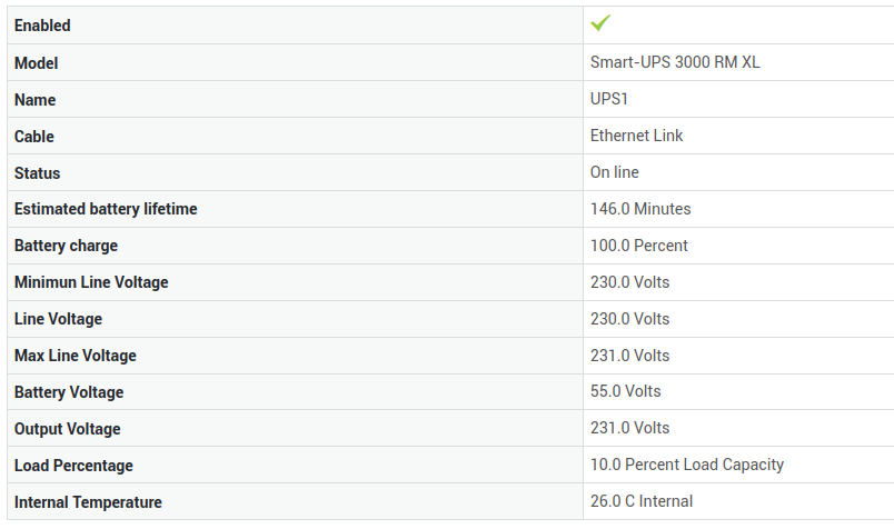
Checking the status of your UPS Device
System administrators can find useful information about the UPS device on the UPS status page, such as the estimated battery lifetime, the current battery charge, etc.
Go to System > Status > UPS to view the status information. Check the configuration of your UPS device if no information is present.
Administrator Tool Configuration
-
Log in to your AXS Guard appliance.
-
Go to System > Administrator Tool.
-
Modify the settings as required and update your configuration. The various options and settings are explained in the table below.
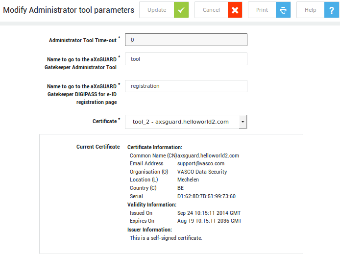
| Field | Description |
|---|---|
| Administrator Tool Time-Out | Specify the inactivity period (in minutes) after which the AXS Guard Administrator Tool automatically disconnects. The default value is 15 minutes. This feature enhances security by preventing unauthorized access if an administrator forgets to log out. To disable the automatic timeout, set the value to 0. |
| Name to go to the AXS Guard Administrator Tool | The name specified in this field automatically resolves to the AXS Guard Administrator Tool when the AXS Guard appliance is configured as your browser’s proxy server. The default value is tool. This hostname is added to the AXS Guard’s internal DNS repository. |
| Name to go to the AXS Guard DIGIPASS Token for eID registration page | Specify the name of the page where users can register their DIGIPASS eID reader. For example, if you enter registration, users can self-register by visiting https://axsguard:82/registration. For additional information, refer to the AXS Guard Authentication guide. |
| Ask for reason when making configuration changes | Enable this option to require administrators to specify a reason when making configuration changes. The provided reason is recorded in the Administrator Tool logs. |
| Certificate | The certificate used to identify your appliance. Go to PKI > Certificates to configure the AXS Guard CA and create certificates. For more information, see the PKI manual. |
Tools Menu
Overview
Four system tools are grouped under the Tools menu:
-
Actions
-
Backup
-
Restore
-
Automatic Reboot
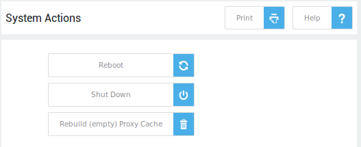
Actions
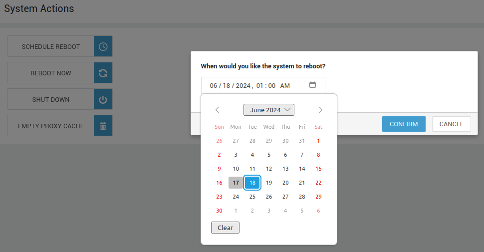
Navigate to System > Tools > Actions. The available actions are described in the table below.
| Button | Description |
|---|---|
| Schedule Reboot | Click to reboot the AXS Guard appliance at a specific time. |
| Reboot Now | Click to reboot the AXS Guard appliance. |
| Shut Down | Click to shut down the AXS Guard appliance. Never disconnect the power supply (power cord) while the appliance is booting up or running, as this may cause system or hardware damage. Always shut down your AXS Guard appliance using this button. |
| Empty Proxy Cache | This option is only available if the Content Scanning Feature (proxy server) is enabled. The proxy cache only needs to be emptied under two conditions: if the cache size has been reduced, or if the cache itself has been corrupted due to an incorrect system shutdown. |
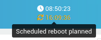
Schedule Reboot
Reboots are sometimes required for system maintenance. You can schedule reboots at your convenience, ensuring minimal disruption during business hours. Simply plan your reboot for a time that best suits your needs. A convenient countdown timer will appear in the top toolbar, keeping you informed of upcoming reboots.
Automatic Reboot
Navigate to System > Tools > Automatic Reboot.

Reboots are required to install software updates and perform periodic filesystem checks of the system's hard drive(s). Automatic reboots can be enabled or disabled, with the day, time, and frequency specified. The date and time of the next scheduled reboot are also indicated.
Activating New Software Options
Additional software options can be purchased and enabled as required. The procedure to activate new software options is explained below.
System administrator(s) are automatically notified by e-mail when new software options are available. The software options need to be activated by a system administrator, which we explain in this section. Once activated, features can be enabled or disabled as required under System > Feature Activation.
-
Log in to the AXS Guard as a full or advanced administrator. A message on the Dashboard will indicate that there are unactivated software options.
-
Click on the
herelink to activate the software options and follow the on-screen instructions.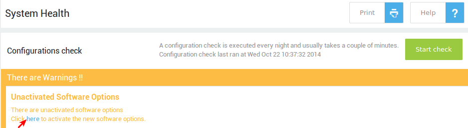
Info
Disabling unused features and options improves system performance.
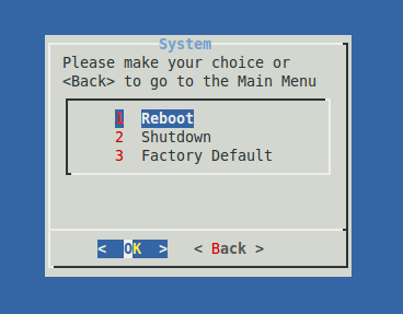
Factory Reset
Important
- Returning your appliance to its factory default state will erase the software license and modify the configuration key.
- Ensure you create a backup of all configuration and user data before initiating a factory reset of your AXS Guard appliance.
- A factory default is not a prerequisite for restoring a backup; the appliance will automatically revert to factory settings as part of the backup restoration process.
The AXS Guard console tool allows you to reset the appliance to its factory default settings. This text-based command-line interface (CLI) provides menu-driven access for editing and displaying critical AXS Guard settings and variables. It also enables the execution of commands for advanced troubleshooting, including network traffic analysis.
Backup and Restore
Overview
Backup and Restore functionalities allow the AXS Guard’s configuration to be saved, and recovered later if necessary. It also allows you to restore a backup to a Spare Unit, in case of a hardware failure.
The Backup and Restore screens are accessible through the System > Tools sub menu. Available options on these screens are explained in the following sections .
Backing up your Configuration
Navigate to System > Tools > Backup to display the Modify Backup screen with tabs for:
-
Backup Download
-
Weekly Backup
-
Daily Backup on Network Share
These and a fourth backup option, backup on Able Servers, are describe in the following sections.
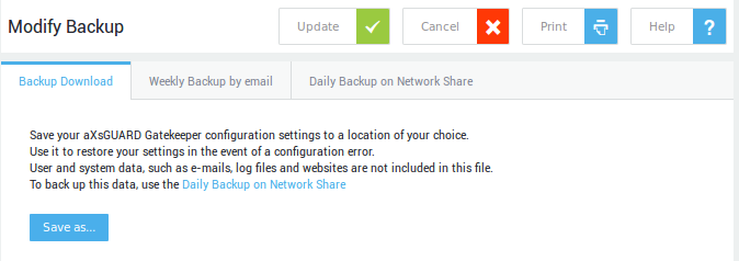
Backup Download
This type of backup does not back up e-mails, log files or any other user data. Use the Daily Backup on Network Share option to back up this data.
Backup Download allows you to save the current AXS Guard configuration settings. The backup file(s) created can later be restored to the AXS Guard if a configuration error occurs. Configuration settings are saved in a compressed .tgz file.
-
Navigate to System > Tools > Backup & Restore > Backup.
-
Click on
Save as. -
Browse to select the location for storing the backup.
Weekly Backup by Email
Weekly Backup by email cannot be used to back up e-mails, log files or any other user data. Only your AXS Guard configuration data is backed up. Use Daily Backup on Network Share to create full system backups.
Via Weekly Backup by email system administrators can specify one or more email addresses to send a backup to.
-
Navigate to System > Tools > Backup & Restore > Backup.
-
Click on the Weekly Backup by email tab.
-
Configure the settings as required. Fields are explained in the table below .
-
Click on Update.
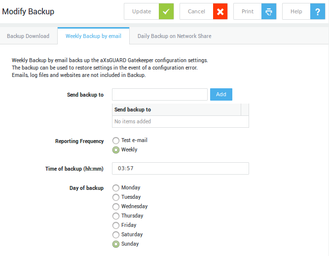
Field |
Description |
|---|---|
Send backup to |
Specify one or multiple e-mail addresses. |
Reporting Frequency |
Two options are available:
|
Time of backup |
The e-mail containing the backup file will be sent at the specified time. |
Day of backup |
The e-mail containing the backup file will be sent on the specified day. |
Daily Backup on Network Share
Daily Backup on Network Share allows you to make a backup of the AXS Guard configuration and critical user data, such as e-mails and log files, to a network share. System administrators receive a report via e-mail when the backup has been completed.
The report is sent to the e-mail address(es) specified on the System > General screen. If an error occurs during the backup process, the type of error is also reported.
-
Navigate to System > Tools > Backup & Restore > Backup.
-
Click on on the Daily Backup on Network Share tab.
-
Enter the Server settings and select the data to be backed up (fields are explained in the table below ).
-
Click on Update. A Create Now button appears at the bottom of the screen, which can be used to create a backup immediately, to test the settings.
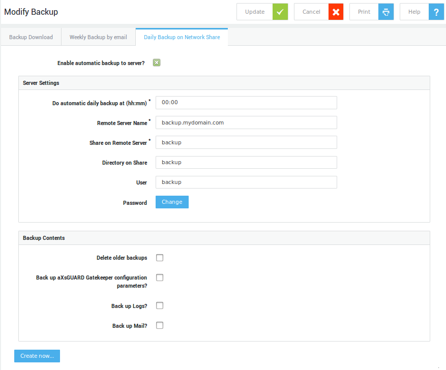
| Server Setting | Description |
|---|---|
| Enable automatic backup to server? | Automatically sends a backup of your configuration and user data to the specified server every 24 hours (if enabled). In the unlikely event of a system crash, you will be able to swiftly recover your settings and user data as they were at the time of the last backup. Enabling this option is highly recommended. |
| Do automatic daily backup at (hh:mm) | Performs a backup at the specified time. Use the hh:mm format. |
| Remote Server Name | The hostname or IP of your backup server. |
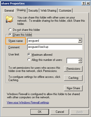
| Share on Remote Server | The name of the SMB share as broadcasted by the backup server. |
| Directory on Share (optional) | Specify a directory within the share. Use this if you shared an entire drive, e.g. d:. This prevents backup data from being written to the root directory of the shared drive. Use \ for subfolders, e.g. backups\axsbackup is valid syntax. |
| User | The username to log in to the backup server. |
| Password | The password to log in to the backup server. |
| Backup Contents | Select the data to be included in the backup. |
Backup options:
-
Delete older backups: old backup files are overwritten if option is enabled (see note below)
-
AXS Guard configuration
-
logs
-
e-mails
-
SSL Web Portal settings
Backups on Able Servers
For customers who subscribe to a Managed Services contract, Able provides an AXS Guard configuration backup service for disaster recovery.
Backups to Able Servers occur every 3 hours for subscribing customers. Only the latest backup is stored on the Able servers; previous (older) backups are removed.
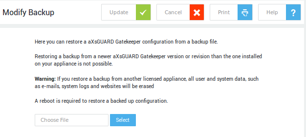
Restoring your Configuration
Restore from File
Important
- Restoring a backup of a different AXS Guard license erases all e-mails, logs and other files stored on the AXS Guard.
- Restoring to a Spare Unit is restricted to the same software version as the appliance being replaced (or a higher version to which data migration is supported; please contact Able support (support@axsguard.com) for guidance).
- Restoring a back-up from another appliance means that the Host Key varies from the Host Key to which the License is bound. In this case the License has a grace period of 30 days. Restoring a back-up from the same appliance means that the Host Key remains the same and re-licensing is not necessary.
- The Configuration Key from the back-up is always restored.
-
Navigate to System > Tools > Backup & Restore > Restore from file.
-
Click on the Browse button to locate the appropriate backup file. Backup files have the extension
.tgz. -
Reboot the appliance.
Restore from Server
Available backups will be shown if you configured your backup server settings under Backup > Daily Backup on Network Share.
Restoring a Backup on a Spare Unit
A Spare Unit is an unlicensed appliance, with limited configuration possibilities and allows you to swiftly replace a defective appliance.
It can also be licensed as a new appliance. In fact, all appliances can be considered spare units until they are fully licensed.
Restoring a backup on a Spare Unit is restricted to:
-
the same hardware version (e.g. AG-3XXX, AG-5XXX or AG7XXX) as the unit being replaced.
-
the same software version as the appliance being replaced (or a higher version on which data migration is supported; please contact Able support (support@axsguard.com) for guidance.
Once a backup is restored on a Spare Unit, full functionality is available. The configuration tool of the appliance can then be accessed by any user with administrative privileges.
The license from the backup is also restored on the Spare Unit. However, an appliance with a restored license only remains operational for a grace period of 30 days, during which the System Administrator needs to acquire a new license. If a new license has not been issued after this grace period, all services on the appliance will be stopped. Only the Administrator Tool will remain accessible.
Contact us (support@axsguard.com) to release the restored license of the original appliance. To relicense the appliance, follow the same procedure as used during first-time licensing.
Software Updates
Introduction
AXS Guard is constantly improving by adding new features, tweaking the user experience and sharpening its functionalities so that it can achieve its end goal as efficiently as possible.
New attacks and methods to exploit software are discovered on a daily basis. Many of the more harmful attacks take advantage of software vulnerabilities in common applications, operating systems, software libraries and browsers. Software updates are therefore the most essential step to take when it comes to protecting your AXS Guard appliance as well as your network environment.
In addition to security fixes, AXS Guard software updates also include new or enhanced features and small patches to improve compatibility with different devices, services or applications. Updates improve the general stability of your appliance and remove outdated features.

Rolling Release Development
AXS Guard is an independently developed security platform based on the Linux kernel and strives to provide the latest stable software to its customers by following a rolling-release model.
The main benefit of a rolling-release model is the ability for administrators to always have the newest version of the software automatically installed. Bugs can be corrected much faster and new features can be rolled out much more efficiently.
Testing, QA & Software Rollout
Testing Levels
AXS Guard uses thousands of tests at different levels to identify areas of weakness. These levels overlap in each phase of the development cycle:
- Unit tests: are used to test individual software modules and to verify if they are satisfying the predefined requirements or not.
- Integration tests: mainly used to test the data flow between software components.
- System tests: used to test the software's functional and non-functional requirements. At this level, the testing environment is parallel to the production environment; the software is tested as a whole system and the end-to-end system specifications are evaluated.
- Acceptance testing: used to evaluate the compliance of the system with the business requirements and to assess whether it is acceptable for delivery or not.
Update Notifications & Release Notes
System administrators are automatically notified by e-mail as soon as software updates are available. A message will also appear on the appliance’s dashboard.
The e-mail contains detailed release notes, which are also available on this site.
Software Rollout
AXS Guard uses a software rollout plan in order to safely implement new software and avoid system downtime. Control mechanisms are implemented for each phase of the rollout. If an issue is detected at any phase, the software rollout activities are stopped immediately.
- Phase 1: Upgrade of internal production systems and appliances assigned to AXS Guard employees.
- Phase 2: Once all upgrades on internal production systems are successful and have been running without any issues for an extended period of time, we gradually start upgrading partner systems.
- Phase 3: If no issues are discovered on the partner systems, we gradually upgrade the customer systems of our partners.
Update Settings
-
Navigate to System > Software Updates.
-
Select
Preferences. -
To check for updates on the fly, click on
Check for updates.
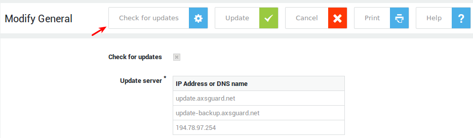
Important
- The software updates menu only exist for backwards compatibility with appliances that are still running old software versions (prior to version 10).
- As software is rolled out automatically as of version 10, these settings should not be changed.
- See the context-sensitive help on AXS Guard for additional information about these options.
Server-Side TLS Options
Introduction
AXS Guard uses TLS to secure a variety of its services, e.g. e-mail and VPN services. System administrators can change the default TLS configuration of the following AXS Guard services:
-
The web-based configuration tool
-
The reverse proxy
-
The AXS Guard MTA
-
The OpenVPN server
Configuration
-
Log in to your AXS Guard appliance.
-
Go to System > Security > TLS.
-
Click on a service to configure its TLS options, which are explained in the tables below.
-
Update your configuration when ready.
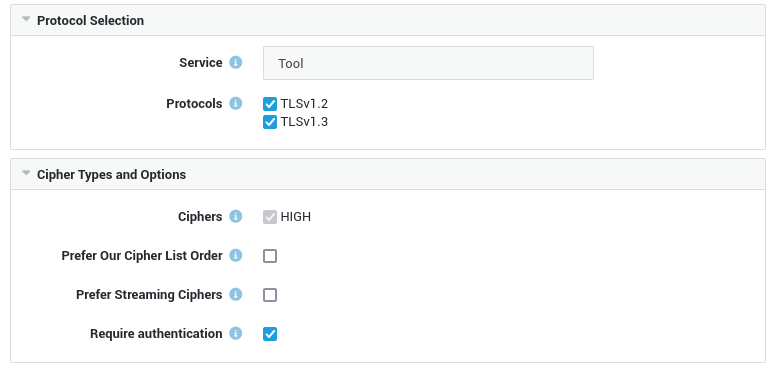
| Protocol Selection | Description |
|---|---|
| Service | The AXS Guard service to which the settings will be applied (System > Security > TLS). |
| Protocols | The TLS version(s) to be supported by the service. Select the ones that should be enforced. |
| Cipher Types and Options | Description |
|---|---|
| HIGH | All ciphers with key lengths larger than 128 bit (and some with 128 bits). |
| Prefer Our Cipher List Order | During SSL negotiation, the client proposes a list of supported ciphers to the AXS Guard service in the order preferred by the client. The service then selects the first compatible one, which may or may not be the strongest cipher supported by both. By enabling this option, the order of the ciphers proposed by the client is overruled and the server offers the strongest cipher first. Note that this may affect older clients or software, which potentially propose a weaker cipher first due to a poor implementation or for reasons of performance. |
| Prefer Streaming Ciphers | In order to mitigate the risk of a BEAST or Lucky13 attack, you can choose a streaming cipher over a block cipher. Such attacks exploit a flaw in the way old TLS versions initialize vectors for CBC block ciphers and allow the unencrypted plaintext to be extracted from an encrypted session. The AXS Guard appliance is protected by default against Lucky13 attacks. Note that TLS version 1 and prior versions (SSL versions 2 and 3) only support 1 widely-adopted streaming cipher, namely RC4, which is obsolete and is known to be vulnerable. This option is disabled by default. |
| Require Authentication | Require cipher types that use authentication. Most notably it disables aNULL ciphers offering no authentication and ADH ciphers allowing anonymous Diffie-Hellman authentication. Authentication is required for all services by default. |
Security Levels and Policies
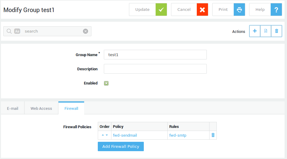
Security Policies
Security Policies define rights for authentication and for data transmission related to the various AXS Guard services, such as e-mail, web access and the firewall:
-
E-mail policies are based on the sender’s and the receiver’s e-mail addresses.
-
Web access and firewall policies can be assigned at the system level, the computer level (based on the computer’s IP address) or - after authentication - at the user level. Authentication allows the configured group or user-specific policies to be assigned. Without authentication, the AXS Guard cannot identify the user, and will assign either computer or system-based policies for Web and firewall access.
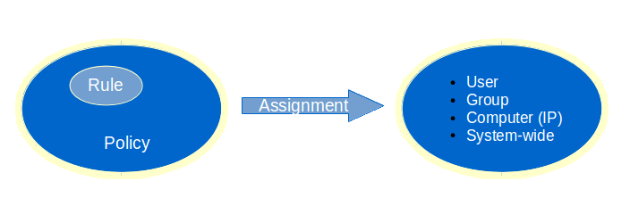
The image below explains the concept of security policies, the rules they contain and their relation to the AXS Guard security levels. In order to link individual rules, which are the smallest configuration element of an AXS Guard feature, to security levels, three simple steps are required:
-
Start by creating the rule(s)
-
Add the rule(s) to a policy
-
Assign the resulting policy to a security level
Info
It is critical to enforce user authentication when possible. A Single Sign-On Tool is available for the AXS Guard to implement Firewall and Web access authentication. This tool allows users to automatically sign-on with the AXS Guard after logging on to their client PC. For more information, please refer to the documents AXS Guard Single Sign-On Utility (SSO) and AXS Guard Authentication How To, available through the permanently on-screen Documentation button.
Security Levels with Authentication
User Level
Settings defined at the user level are specific for a single user and determine special access rights or restrictions for a user on the network (i.e. exceptions). The AXS Guard applies the appropriate Security Policy, which defines a user’s rights, based on the user credentials.
-
Navigate to Users & Groups > Users
-
Select the appropriate user from the list
-
Adjust the settings as appropriate (see User and Group Management ).
Group Level
An AXS Guard group is a logical unit of users who need the same access rights or restrictions on the network. The purpose of using groups is to simplify access control configuration and management. The AXS Guard retrieves the Security Policy, which defines a group’s access rights based on the user credentials and the user’s group membership.
-
Navigate to Users&Groups > Groups
-
Select the appropriate group from the list.
-
Adjust the settings as appropriate).
Security Levels without Authentication
Computer Level
Important
We recommend enforcing user authentication when possible, as this is the most secure option.
Registering a computer on the AXS Guard allows a policy to be applied to the computer, e.g. firewall rights or the right to use the AXS Guard RADIUS authentication service (for more information about RADIUS authentication, please refer to the AXS Guard Authentication How To, available via the Documentation button).
An unauthenticated user on a registered computer is assigned computer-level Web access and firewall policies, based the computer’s IP address. Assigning rights at the computer level (based on the host’s IP address) is therefore less secure than assigning them at user level, because unauthorized users with physical access to the computer could access the network.
Computer registration and computer level assignment of security policies should only be used for servers which:
-
have a static IP address
-
need specific access to services on the Internet, e.g. to download critical system updates.
To change computer-specific policy settings:
-
Navigate to Computers
-
Select the appropriate computer from the list
-
Adjust the settings as appropriate.
System Level
Important
We recommend enforcing user authentication when possible, as this is the most secure option.
A security policy is applied by default at the system level only if a policy has not been assigned at any other level. The system level must enforce the tightest security, as the defined policies at this level are valid for all computers which are physically connected to your network. A user who is physically connected to your network and who does not authenticate, is automatically assigned system-level access rights if his/her computer is not registered on the AXS Guard.
System-specific policy settings are configured separately for each feature, e.g. for the firewall, Web access etc. For further information, please refer to the relevant AXS Guard How To guide, available via the permanently on-screen Documentation button.
Example Configurations
The following two examples demonstrate a user-specific configuration and the efficiency of using groups to assign Security Policies to multiple users.
Example 1
A company has a dedicated group for its Accounting department. The group consists of 5 users. All users of the group are subject to the same Firewall Policy. However, one user (Bob) needs special access to an Internet server which is forbidden by the Group Policy.
To allow access for user Bob:
-
Create a new firewall rule(s) allowing access to the specific server
-
Add the rule to a security policy.
-
Select Add to Group Firewall Policies, in the user’s Firewall profile.
-
Add the newly created security policy. This combines the group and the user-specific policies.
The result is that the user can access the specific server, while he/she is still subject to his Group’s Firewall Policy. For detailsabout firewall rules and policies, please refer to the AXS Guard Firewall How To, which is available via the Documentation button.
Example 2
An office of 500 users is divided into 6 groups. Every user needs access to the AXS Guard e-mail system. This means that you must create of 1 firewall rule per service, i.e. POP, IMAP, SMTP, LDAP (for the address book), which amounts to a total of 4 rules.
-
Without Firewall Policies: creating 4 rules, and adding them to 500 users would require 2004 configuration steps.
-
With Firewall Policies at the group level: creating 4 rules, adding them to 1 Firewall Policy and subsequently assigning the Policy to 6 groups requires only 11 configuration steps.
User and Group Management
Overview
In this section we:
-
define AXS Guard users and groups
-
list the advantages of assigning security policies at the user and group levels
-
explain the general settings for users
-
explain how to create and modify users and groups
-
explain how user and group templates can speed up configuration
For settings specifically related to AXS Guard features such as e-mail or Web access, please refer to the relevant AXS Guard How To guide available via the Documentation button.
Users
An AXS Guard user is a person who:
-
Is registered on the appliance, either manually via the administrator tool or automatically though synchronization with a directory server (LDAP). For information about user synchronization, see the AXS Guard Directory Services How To, which is available via the Documentation button in the administrator tool.
-
Has certain access privileges (firewall, web access, e-mail, etc.) based on his/her profile and group settings.
-
Has a mailbox (if the e-mail server feature is activated on your appliance).
User templates, in which common access rights and other user-specific settings are specified, allow administrators to configure the system more easily.
Groups
An AXS Guard group is:
-
A logical set of users, based on their location, department, access rights or position within an organization, e.g. accountants, the HR division, the legal department, management, etc.
-
Linked to a set of permissions or restrictions which apply to its members.
Groups can be created with the AXS Guard administrator tool or can be imported from a Directory Server. For more information on group synchronization, see the AXS Guard Directory Services How To, which available via the Documentation button.
Group templates, in which access rights and other group-specific settings are specified, can help administrators to easily configure common group settings.
The relationship between user and group level policies are feature-specific. For example, with firewall access, group level policies can be overruled, enforced, or fine-tuned. For web and e-mail access, group level policies can be enforced or overruled at the user level, but cannot be added. For more information, see the relevant AXS Guard How To guides, which are available via the Documentation button.
A group can also consist of a single user.
User and Group Level Security
Assigning security policies at the computer level is insecure. Therefore Able recommends assigning security policies at the user or group levels with authentication.
Advantages inherent to user and group level security are:
-
Authentication (identification of the user) is enforced, which is the most secure option. Strong user authentication, e.g. Able DIGIPASS can be easily implemented.
-
Physical access to a computer is insufficient to obtain network access, i.e. credentials always have to be provided before access is granted.
-
A list of users and/or groups is easier to maintain than a list of computers.
-
Users who share a computer, e.g. at a reception desk, can be assigned different user-specific rights. (Assigning a computer level security policy assigns the same rights to all (unauthenticated) users of the computer, which is insecure).
User & Group Preferences
Navigate to Users & Groups > Preferences. The options are explained in the table below.
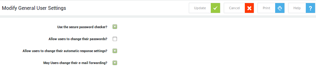
| Field | Description |
|---|---|
| Allow Users to Update their Password | If enabled, users will be allowed to update their AXS Guard password. Note that user-level access to the AXS Guard web-based administrator tool is required in order for users to be able to update their password. To enable access, go to Users & Groups > Users, select the appropriate user, then the AXS Guard administration tab and set the tool access type to 'user'. |
| Allow Users to Update their Auto-response Configuration | This option is only available if the e-mail feature is activated and allows users to change their auto-response settings. With auto-response enabled, e-mail correspondents can be notified automatically when a recipient is unavailable. Note that user-level access to the AXS Guard web-based administrator tool is required in order for users to be able to update their auto-response options. To enable access, go to Users & Groups ▸ Users, select the appropriate user, then the AXS Guard administration tab and set the tool access type to 'user'. |
| Allow Users to Update their Forwarding Addresses | This option is only available if the AXS Guard e-mail server feature is enabled. If checked, users will be allowed to modify their e-mail forwarding options. Note that user-level access to the AXS Guard web-based administrator tool is required in order for users to be able to update their forward addresses. To enable access, go to Users & Groups > Users, select the appropriate user, then the AXS Guard administration tab and set the tool access type to 'user'. |
Password complexity criteria
To improve security, please create strong passwords that meet the following criteria:
-
It must be at least 12 characters long.
-
It cannot be the same as your username.
-
It must not contain a dictionary word.
-
It should not be a common or simple password (e.g.,
password123456789). -
It cannot contain the
#symbol.
You can make your account more secure by using OATH or DIGIPASS tokens for two-factor authentication (2FA). This method is the most secure because it generates a unique, one-time password for every login. For a full guide on how to set this up, check out the AXS Guard User Authentication manual.
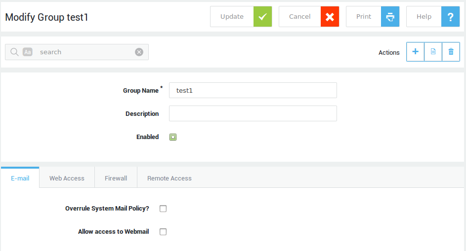
Creating and Editing Groups
-
Navigate to Users & Groups > Groups
-
Click on Add New.
-
Enter the settings as explained below.
-
Click on save when finished.
Important
See the relevant documentation for additional information about feature-specific options.
| Parameters | Description |
|---|---|
| Group Name | A name for the new group. Invalid names will trigger a validation error. |
| Description | Describe your group, e.g. Human Resources. This field is optional. |
| Enabled | If unchecked, group members will be prevented from logging in. |
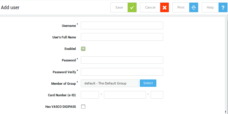
Creating and Editing Users
-
Navigate to Users & Groups > Users
-
Click on Add New.
-
After you have configured the settings as required, click on Save.
Important
- To speed up the creation of new users, administrators can define a user template. A user template is a collection of the settings which all users have in common.
- See the relevant documentation for additional information about feature-specific options.
- The UPN format cannot be used to authenticate for PPTP and AXS Guard services for which Kerberos authentication has been enforced.
| Format | Description and Examples | When to use |
|---|---|---|
User account name |
Also known as the logon name, e.g. |
This format must be used for authentication when the AXS Guard system domain matches the domain of the directory server of which the user is also a member or if the AXS Guard appliance is not synchronized with a directory server. |
User Principal Name (UPN) |
The UPN format is used to specify an Internet-style name, such as |
This format must be used for authentication when the AXS Guard system domain does not match the domain of the directory server of which the user is a member. Note that this format can only be created through synchronization with a directory server; it cannot be entered manually. |
Administrative Privileges
In the AXS Guard Administration tab on the lower part of the Add User screen you can configure:
-
Tool Access Type settings: These settings determine whether or not a user has access to the AXS Guard web-based administrator tool.
-
Console Tool Access: Only for basic administrators or above. If enabled, the user has access to the appliance’s console for advanced troubleshooting.
-
Technical Mailings: Select which messages to receive from Able, e.g. information about critical updates.
-
Access to FTP files: System legacy option.
| Tool Access Type | Description |
|---|---|
None |
The user has no access to the administrator tool. |
User |
The user can only modify his/her full name, auto-response settings, password and e-mail forwarding settings, if allowed by the system administrator. |
Reporting User |
A reporting user has the same access as a regular user, but also has access to web access, e-mail and the AXS Guard hardware performance statistics. |
Distribution List Administration |
This option is only available if the AXS Guard e-mail feature is enabled. This user type has the same access rights as a reporting user and can manage e-mail distribution lists. |
Basic Administration |
This user type only has restricted administrator access. At this level, only non-critical system settings may be modified, e.g. user and group settings. |
Full Administrator |
This is the default administrator type. All standard system settings can be modified or viewed. |
Advanced Administrator |
Caution: Only expert administrators should be assigned allowed this type of access. Advanced administrators can view and modify system-critical settings, which are typically never modified, e.g. DNS forwarding. |
Access to FTP files
FTP access can be used to download AXS Guard log files, e.g. firewall logs. FTP access towards the AXS Guard is only possible if allowed by the firewall.
Options for FTP access are displayed under the AXS Guard Administration tab in the lower part of the Add User screen.
| FTP Access Option | Description |
|---|---|
No FTP Access |
Access to FTP is denied. |
Unrestricted FTP Access |
Provides access to the AXS Guard logs and the IMAP mail directories (only if the AXS Guard e-mail feature is enabled under System > Feature Activation). |
Intranet-Extranet FTP access |
Allows the user to upload and download files to and from the AXS Guard Intranet and Extranet areas (legacy option). |
Console Tool Access
The console tool is a text-based command line interface (CLI) to edit and display critical AXS Guard configuration parameters via menus. It also allows you to execute commands for advanced troubleshooting, such as network traffic analysis.
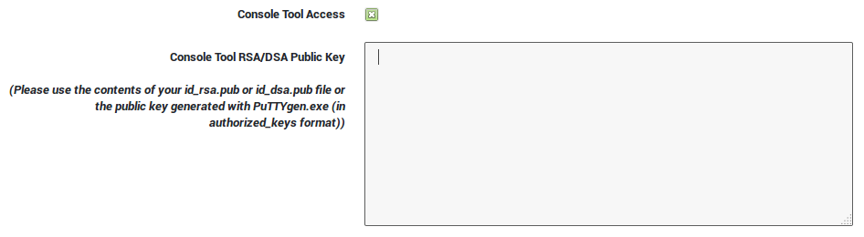
Parameter |
Description |
|---|---|
Console Tool Access |
Check to enable access to the console tool. |
Console Tool RSA/DSA Public Key |
Copy and paste the user’s public key, generated with |
User and Group Templates
AXS Guard user and group templates allow administrators to easily configure common user or group settings. Examples of common settings are firewall access rights, web access rights and e-mail policies. The template system prevents you from repeatedly having to define identical settings for different users and groups, thus simplifying configuration. The template settings are automatically applied each time a new group or user is manually created or synchronized with a directory server.
The template system is particularly useful for synchronizing a large number of users and groups with a Directory Server, such as Active Directory. For information about user and group synchronization, see the AXS Guard Directory Services How To, available via the Documentation button.
System administrators need to determine which AXS Guard privileges and services are shared by most AXS Guard groups and users. If a certain user or group needs special access (or must be denied access) to a specific resource, it is easier to define and assign the exception(s) afterwards. For information on how to configure user and group templates, see the following sections.
You can create one user template and one group template per LDAP profile. The AXS Guard provides default user and group templates which can be modified to accommodate your specific needs.
Group Template Settings
Modification of the default group template does not affect existing AXS Guard groups. The group template is only applied when a new group is created.
-
Navigate to Users and Groups > Groups.
-
Click on the Template button as indicated below.
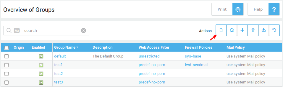
-
Configure the group settings as required.
-
Click on Update to finish. (The system may display a validation warning to counter potentially dangerous configurations, which need to be modified before you can continue.)
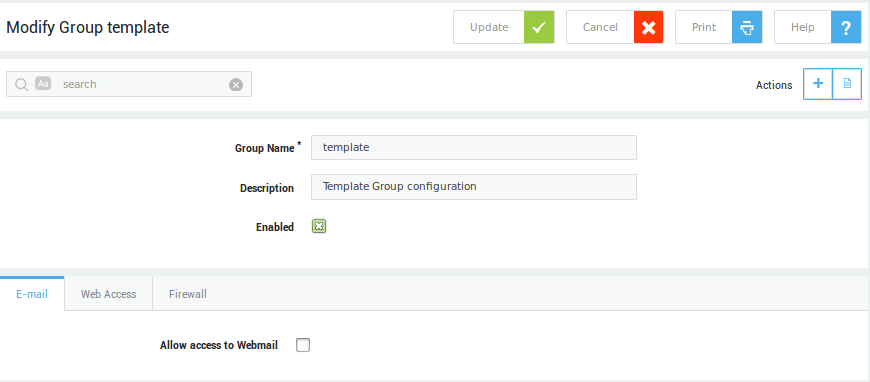
The number of tabs available on your system may vary depending on which features are activated on your AXS Guard appliance. Go to System > Feature activation for an overview of activated features on your system.
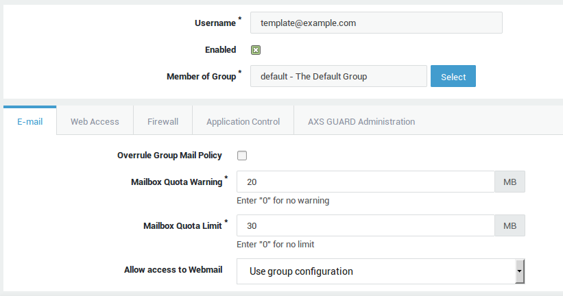
User Template Settings
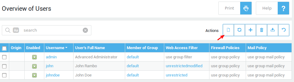
Modification of the user template does not affect existing AXS Guard users. The user template is only applied to new users.
-
Navigate to Users and Groups > Users
-
Click on the Template button as indicated below.
-
Configure the user settings as required. Tabs on the Modify User Template screen may vary depending on the features which are activated on your AXS Guard. For more information about feature-specific settings, see the relevant AXS Guard How To guides available via the Documentation button.
-
Click Update to finish. (The system may display validation warnings to counter potentially dangerous configurations, which need to be modified before you continue).
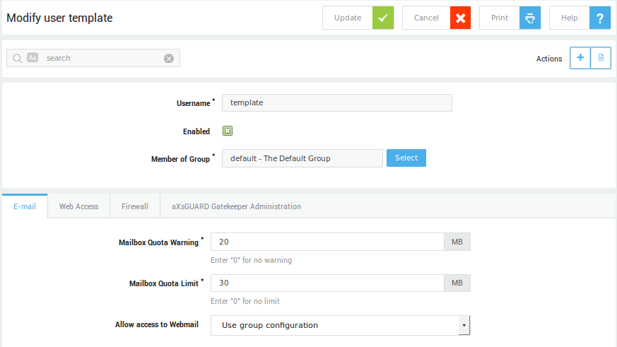
The number of tabs available on your system may vary depending on which features are activated on your AXS Guard appliance. Go to System > Feature activation for an overview of activated features on your system.
Computer Management
Overview
In this section, we explain:
-
when computers need to be registered on the AXS Guard
-
the disadvantages of assigning security policies at the computer level, and
-
how to register a computer on the AXS Guard.
For settings specifically related to AXS Guard features such as e-mail or Web access, please refer to the relevant AXS Guard How To guide, available through the permanently on-screen Documentation button.
When to register a computer
Able strongly recommends enforcing user authentication whenever possible rather than assigning security policies at the computer level.
Registering computers on AXS Guard allows rights and restrictions to be assigned through security policies. Security policies control network access from the computers, such as the firewall rights or the right to use the AXS Guard RADIUS authentication service. (For more information on RADIUS authentication please refer to the document AXS Guard Authentication How To, available through the permanently on-screen Documentation button.)
Assigning security policies at the computer level is only appropriate for servers (with a static IP address) which need specific access, e.g. for the use of the RADIUS service on the AXS Guard. In all other instances, Able recommends assigning security policies at user and group levels and enforcing user authentication.
It is not necessary to register computers from which users authenticate, as access rights in this case are determined based on the user credentials provided.
Computer Level Security
Disadvantages inherent to computer level security are:
-
The authentication process (identification of the user) is bypassed, which is insecure.
-
Physical access to a computer is sufficient to acquire possibly more rights than normally permitted with user authentication and could lead to unauthorized access to network resources or to abuse of your network’s public IP address.
-
A computer list may lead to errors and is difficult to maintain (DHCP), while a user list is not (especially for large networks).
-
It is not possible to assign different rights to multiple users who use the same computer, e.g. a reception desk. This is only possible with user authentication.
-
Troubleshooting is more difficult and cumbersome, since access rights can be configured at the user, group and computer level.
It is imperative to enforce user authentication wherever possible. A Single Sign-On Tool is available for the AXS Guard to implement Firewall and Web access authentication. This tool allows users to automatically sign-on with the AXS Guard after logging on to their client PC. For more information, please refer to the documents AXS Guard Single Sign-On Utility (SSO) and AXS Guard Authentication How To, available through the permanently on-screen Documentation button.
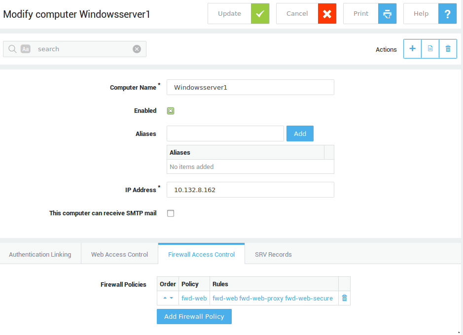
Registering Computers
Important
- Only servers (with a static IP address) should be registered on AXS Guard.
- Enforce authentication for regular computers, such as workstations.
-
Navigate to Computers.
-
Click on Add new.
-
Configure the settings as explained in the following tables.
-
Click on Save.
The number of tabs available under Computers are linked to the features that are activated and may vary on your AXS Guard appliance. Go to System > Feature Activation for an overview of enabled features on your system.
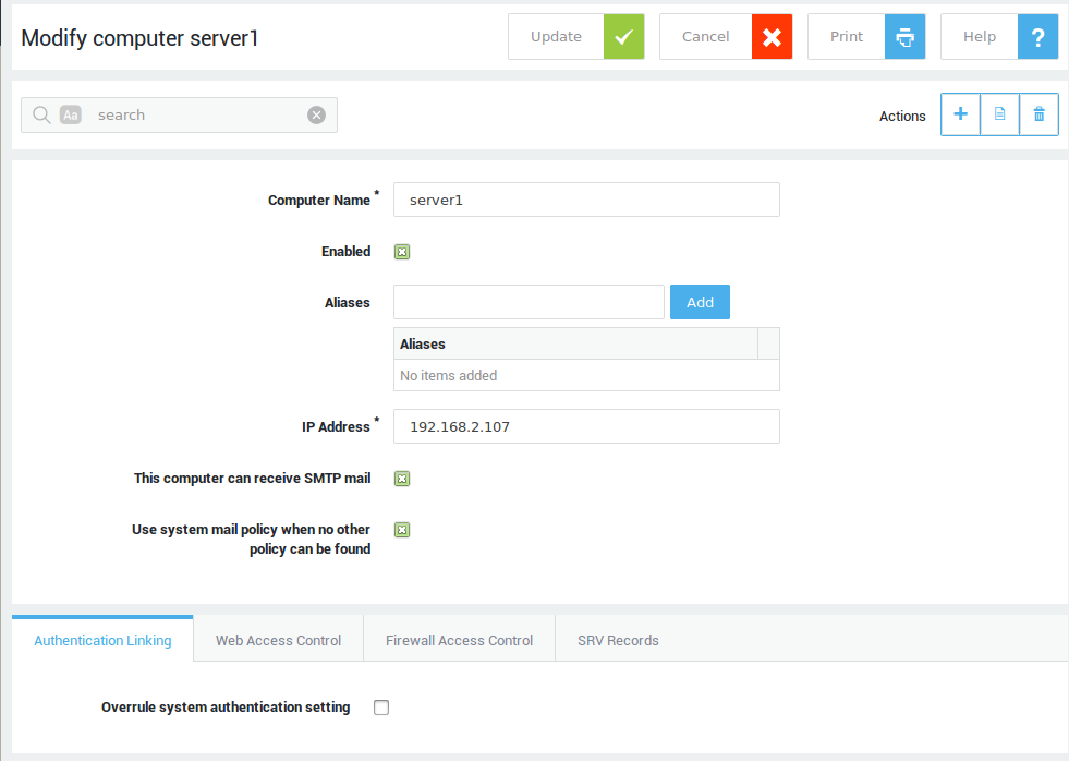
General Settings
| Field | Description |
|---|---|
Computer Name |
Enter a name for the computer, using lower cases without spaces, starting with an alphabetic character, followed by any number of alphanumeric characters and/or the special characters: hyphen (-) and full stop(.) If possible, use the name of your computer, as defined in your Network / Properties / Identification tab (where the computer name is listed) since this is usually unique. The entered computer names and aliases are added to the internal DNS system of the AXS Guard appliance. |
Enable Computer |
Check to enable (default setting). Uncheck to disable. If disabled, system-level or user-level policies will be applied for web access, authentication, the firewall and SRV records. When a computer is disabled, its SRV record is not added to the internal DNS repository of the AXS Guard appliance. |
Alias Names |
You can add several names for a computer, providing the names adhere to the same specifications as for the Computer Name (see field above). All aliases are added to the AXS Guard internal DNS server. Computer names, computer aliases, device names and device aliases need to be unique in the network. |
IP address |
Enter the IP address of the computer to be added. IP addresses of computers must be unique. If you want a certain IP address to be known under (a) different name(s), the name(s) can be added in Alias Names as described above. |
This computer can receive SMTP mail |
Enable this option if the computer is running an SMTP mail server. This may be the case, for example, if the mailboxes on the AXS Guard appliance aren’t used, but e-mail is forwarded from the AXS Guard appliance to an Exchange server instead. For more information, see the AXS Guard E-mail Relay How To, available via the permanently on-screen Documentation button. |
Use system mail policy when no other policy can be found |
This option is only visible if the option above is enabled. Enable the option if the computer is a mail server where each user can control his/her own e-mail forwarding. In this case, e-mails could be sent to the AXS Guard mail content filtering system where both the sender and recipient addresses don’t belong to local or forwarded domains. Without activating this option, these e-mails would be blocked, as no mail policy is assigned. Activating this option will enable the AXS Guard to handle the computer’s mail traffic using the system mail policy as defined under E-mail > General. |
Authentication Linking
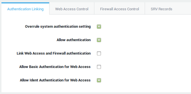
| Field | Description |
|---|---|
Overrule system authentication setting |
AXS Guard firewall and web access authentication can be combined (linked) or separate (unlinked). Check to link authentication for users of this computer. This configuration overrules the system-wide configuration under Web Access > General. |
Allow authentication |
Uncheck to block all authentication requests from this computer. |
Link Web Access and Firewall authentication |
Linked authentication is the default configuration and combines authentication for firewall and web access privileges. With linked authentication, users are mapped to the computer’s IP address from which they authenticate, making the user and IP address a unique pair. Based on this unique pair, the defined firewall and web access rights are assigned to the user after successful authentication. |
Allow Basic Authentication for Web Access |
This option is only available with unlinked authentication. Users will be invited to authenticate via a browser popup when they attempt to access the Internet via the AXS Guard proxy server. Configured computer ACLs don’t apply in this case. Web access is only authorized after authentication, including access to sites configured in system-wide ACLs (under System > Web Access > General). After authenticating, the user’s group and / or user level ACLs are applied. If no user or group ACLs exist, the system-wide ACLs are applied. |
Allow Ident Authentication for Web Access |
The Ident Protocol, defined per RFC 1413, is an Internet protocol that helps to identify the user of a particular TCP connection. This simplifies management in that you do not have to match IP addresses to computers to regulate web traffic. Using Ident has several benefits over the SSL (SSO) or proxy login methods, primarily that the user does not need to enter username and password credentials for Web Access. Instead, an Ident server running on the citrix client system will automatically relay the Windows username to the AXS Guard proxy. |
Web Access Control
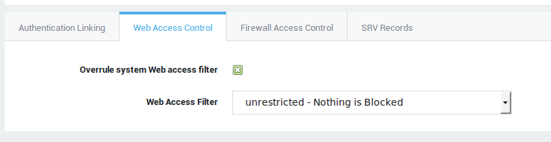
| Field | Description |
|---|---|
Overrule system Web access filter |
Check to overrule the system-wide web access filer defined under Web Access > General. |
Web Access Filter |
Select the desired web access filter from the drop-down list. Go to Web Access > Filters > ACL for an overview of configured web access filters. |
Firewall Access Control
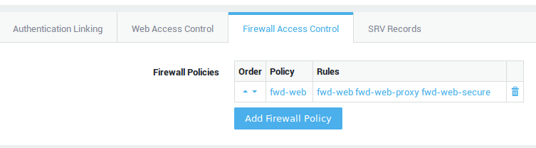
| Button | Description |
|---|---|
Add Firewall Policy |
Select the desired firewall policy from the drop-down list. Go to Firewall > Policies > Dynamic for an overview of assignable firewall policies. |
Application Control
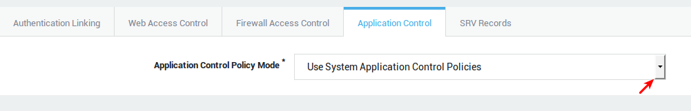
| Option | Description |
|---|---|
Use system application control policies |
Use the system-wide policies, assigned under Application Control > General. |
Add to system application control policies |
Assign specific policies to this computer, in addition to the system-wide policies configured under Application Control > General. |
Overrule system application control policies |
Do not enforce the system-wide policies, but only the specified policies. Specific policies are enforced based on the computer’s IP address. |
SRV Records
You can add SRV records to the Internal DNS server of your appliance. SRV Records extend DNS functionality to enable location of services outside of the standard record types supported in DNS. Various protocols such as SIP and XMPP use SRV records to allow discovery of the service endpoint for a particular domain. The SRV record is defined in RFC 2782.
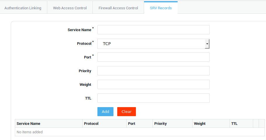
| Field | Description |
|---|---|
Service Name |
The symbolic name of the desired service. |
Protocol |
Select the transport protocol of the desired service from the drop-down list; TCP or UDP. |
Port |
The TCP or UDP port on which the service is to be found. |
Priority |
The priority of the target host. A lower value means a higher priority. |
Weight |
A relative weight for SRV records with the same priority. A higher value means more weight. |
TTL |
Standard DNS time to live field. |
Example of an SRV record
_sip._tcp.example.com. 86400 IN SRV 0 5 5060 sipserver.example.com.
Network Configuration
Introduction
In this chapter, we explain the various network settings. Topics covered in this section include:
-
Network devices that you may find on your appliance
-
How to configure Ethernet, Virtual Local Area Network (VLAN) and PSTN devices. (The number of available network devices varies per model. Each appliance has at least two Ethernet network devices and one or more PSTN devices).
-
How to configure the internal DNS repository (Domain Name System).
-
How to configure the DHCP server.
-
The basic principles of routing.
-
How to configure NAT (Network Address Translation).
Supported Network Devices
Physical Devices
-
PSTN devices
-
Ethernet devices
-
Bridges
-
Bond devices
Virtual Devices
-
VLAN devices.
-
TUN devices: A TUN device is a virtual point-to-point IP link used by the Personal aXsGUARD (PAX).
-
TAP devices: A TAP device is a virtual ethernet adapter used by the OpenVPN server.
-
PPTP devices: used by PPTP client and servers. For information about PPTP, click on Documentation to download the PPTP How To.
-
e-tunnel devices: Special devices used by IPsec e-tunnels. See the IPsec How To for more information.
-
IPsec devices: Devices used for IPsec tunnels and L2TP. See the respective manuals for more information.
-
PPPoE devices: The Point-to-Point Protocol over Ethernet (PPPoE) is a network protocol for encapsulating Point-to-Point Protocol (PPP) frames inside Ethernet frames. It is used mainly with DSL services.
Ethernet Devices
Configuration
-
Navigate to Network > Devices > Eth.
-
Click on a logical device in the list. A screen similar to the image below appears.
-
Configure the settings as explained in the following sections on:
-
general settings
-
interface types
-
connection settings such as the speed, duplex mode and MTU
-
IP settings
-
account settings
-
connectivity checks
-
-
Click on Update.
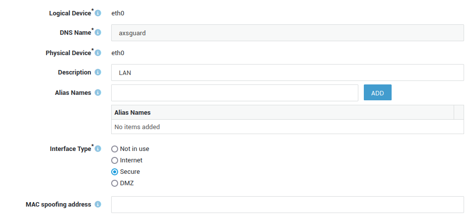
General Settings
Changing the configuration of network devices requires the system to be rebooted.
| Field | Description |
|---|---|
Logical Device |
The name of the physical device. FYI only. This name cannot be changed. |
DNS Name |
The name of the device as known by the AXS Guard DNS server. Changing this will restart the DNS service. |
Description |
A description for the device (optional). |
Alias Names |
Alias(es) for the DNS name. Use the Add button to specify multiple aliases. |
Interface Types
- Not in use: Select this option to disable the device.
- Internet: Select this option if the device is connected to the Internet, for example your DSL modem. This device can either be assigned a public or a private IP address (e.g. in NAT environments). Multiple Internet devices can only be configured if the Internet Redundancy feature is enabled under System > Feature Activation.
- Secure: The network device to which all your company workstations are connected, shielded from the Internet by the firewall of the appliance. This device has an IP address in the private range.
192.168.250.254/24is the factory default IP address. - DMZ: This network device can either be assigned a public or private IP address. The DMZ is an insecure area where you would install a public server for which the AXS Guard Reverse Proxy cannot be used.
Interface Types
If the AXS Guard appliance is used for authentication only, there is only one secure interface. Interface settings for the Internet and DMZ are not relevant in this case. For more information about AXS Guard authentication services, see the AXS Guard Authentication How To, which can be accessed via the on-screen Documentation button.
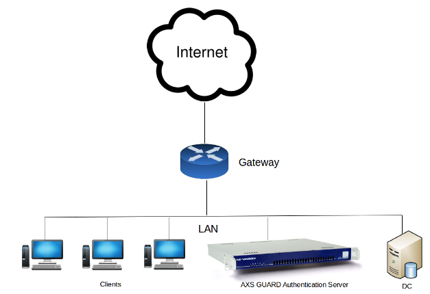
If the AXS Guard appliance sits at the gate of your network, as illustrated below, configure the interface type according to the network to which it is connected, i.e. the Internet, the Secure LAN or the DMZ.
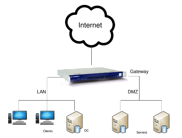
MAC Spoofing Address
MAC address spoofing enables you to replace devices without needing to update the authorized MAC address with your service provider. The original MAC address can be viewed on the Network > Status > Devices page. If the MAC address change process encounters an error, it will be shown on the dashboard.
Connection Settings
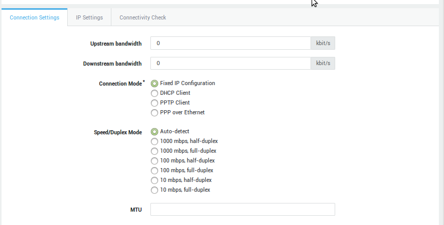
Setting |
Description |
|
|---|---|---|
Upstream bandwidth |
This parameter is only relevant if you are using bandwidth management, which must be enabled under System > Feature Activation. The upstream bandwidth is the maximum amount of data which can be sent through the device per second (expressed in Kilobits per second). A value of |
|
Downstream bandwidth |
Only relevant for bandwidth management. The downstream bandwidth is the maximum amount of data which can be received by the device per second (expressed in Kilobits per second). A value of |
|
Connection Modes |
Fixed IP Configuration: Select this option to assign a static IP address to the network device. |
DHCP Client: DHCP is an Internet protocol that allows IP addresses to be assigned dynamically by a DHCP server (Defined per RFC 2131). Select this option to dynamically assign an IP address to the device. |
PPTP Client (Internet Only): In some countries, Internet Service Providers use PPTP to connect their customers to the Internet. Enter the correct IP and account information. Contact your Internet Service Provider if you are unsure about the account information. |
||
PPP over Ethernet (Internet Only): PPPoE is a network protocol for encapsulating Point-to-Point Protocol (PPP) frames inside Ethernet frames. It is used mainly with ADSL services where individual users connect to the ADSL transceiver (modem) over Ethernet. Contact your ISP if you are unsure about the account information. |
||
Speed / Duplex Mode |
The factory default setting is auto-detect, which negotiates the speed and duplex settings for the highest possible data rates. For this mode to function properly, you must also configure the other endpoint (switch) so it uses automatic negotiation as well.
|
|
MTU |
Packet size, often referred to as MTU (Maximum Transmission Unit) is the greatest amount of data that can be transferred in one physical frame on the network. For Ethernet, the MTU is 1500 bytes, for PPPoE 1492, dial-up connections often use 576. 1500 is assumed when no value is specified. |
IP Settings
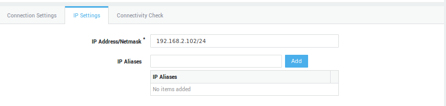
Field |
Functionality |
|---|---|
IP Address/Netmask |
The appliance’s IP address as seen from a network zone connected to the Ethernet device. Use the CIDR notation to specify the netmask. A netmask of |
IP Aliases |
Use this field to assign additional IP addresses to the network device. Aliases are used to connect several subnets (network segments) to the same Ethernet device. Use the CIDR notation to specify the netmask. A netmask of |
Gateway |
If the Interface Type is set to Internet, enter the IP address of the gateway provided by your Internet Service Provider (ISP). Contact your ISP if you are unsure about the gateway IP. If the Interface Type is not set to Internet:
|
Account Settings
Account Settings can only be configured if one of the following connection modes has been selected:
-
PPTP Client
-
PPPoE
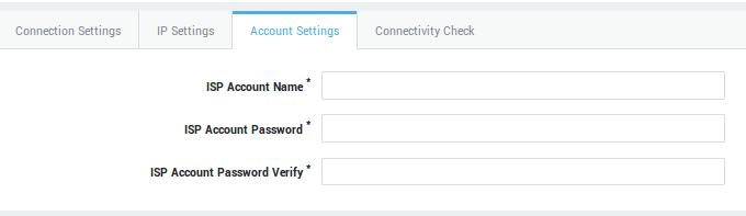
| Field | Description |
|---|---|
ISP Account Name |
Enter the account name (login) provided by your ISP. |
Password |
Enter the password provided by your ISP (twice for verification). |
Connectivity Check
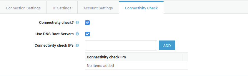
| Field | Description |
|---|---|
Connectivity Check |
Connectivity checking is a functionality which periodically tests whether the network interface still has connectivity or not. This option cannot be disabled for Internet devices. If enabled, the AXS Guard appliance will periodically send ICMP (ping) messages to the specified IP address(es). System administrator(s) will be notified by e-mail if connectivity is lost. Timeout values can be configured under Network > Monitoring. Do not use master or slave IP addresses for network connectivity checks (also see High Availability > General ). |
Use DNS Root Servers |
If enabled, DNS root servers will be used to periodically check the connectivity of the selected Internet interface. |
Connectivity Check IPs |
Enter the IP address(es) to be used for connectivity checks. Do not use master or slave IP addresses for network connectivity checks (also see High Availability ▸ General ). |
Virtual Local Area Networks (VLANs)
About
A Virtual Local Area Network (VLAN) device is an independent network interface, with its own configuration parameters and is used to add one or more segments to your network without the need to add an additional physical network interface.
A Virtual LAN device is always added to a physical LAN device, for instance eth0. VLAN devices use their own identifiers for communication, e.g. eth0.10. It's important to note that the range of VLAN IDs that are allowed can vary depending on the specific networking equipment and configuration being used.
Some switches may have further restrictions on which VLAN IDs are allowed, so it's always a good idea to consult the documentation for your specific networking equipment to determine the range of VLAN IDs that are supported.
Adding VLAN Devices
-
Navigate to Network > Devices > Eth
-
Select the device in the list to which the VLAN should be added, e.g.
eth0 -
Click on the Add Virtual LAN button (shown below).
-
A VLAN device requires the same configuration parameters as an Ethernet device. Only the Virtual LAN identifier is VLAN-specific. Some VLAN identifiers are reserved and should not be used, e.g.
eth0.0,eth0.1. -
After configuring the relevant settings, click on Save.
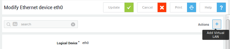
| Field | Description |
|---|---|
Logical Device |
The name of the VLAN device as known by the appliance, e.g. |
VLAN on Physical Device |
The physical network device to which a VLAN device is added, e.g. |
Virtual LAN Identifier |
A VLAN identifier is a unique number to identify a VLAN device in a network. Use a VLAN identifier equal or greater than 10, e.g. |
About VLAN Identifiers
A VLAN identifier is a unique number to identify a VLAN device in a network.
-
Always use a VLAN identifier equal or greater than 10, e.g.
eth0.11. VLAN identifiers ranging from 0 to 9 are reserved by some manufacturers and could cause the VLAN to malfunction if used. Consult the documentation for your specific networking equipment to determine the range of VLAN IDs that are supported. -
The logical device, e.g.
eth0.11, is the name of the device as recognized by the AXS Guard Operating System.
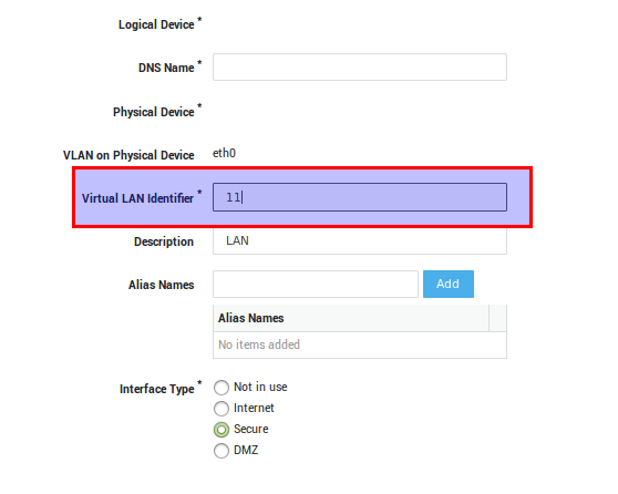
Channel Bonding
Concepts
Channel bonding or Ethernet bonding is a computer networking arrangement in which two or more network interfaces on a host are combined for redundancy or increased throughput. Bonding allows you to effectively combine the bandwidth into a single connection or to create multi-gigabit pipes to transport traffic through the highest traffic areas of your network.
You can aggregate three megabits ports (1 mb each) into a three-megabits trunk port. That is equivalent to a single three megabits interface.
-
Provides redundant links
-
Fault tolerance
-
Load balancing
It is the best way to have a high availability network segment. A very useful way to use bonding is to use it in connection with 802.1q VLAN support (your network equipment must support the 802.1q protocol).
-
A given network device can only be added to a single bond device.
-
Only free network devices can be added to a bond device (not in use).
-
A bonding device can only be connected to another bonding device, i.e. all participants must have a bonding device, as illustrated below.
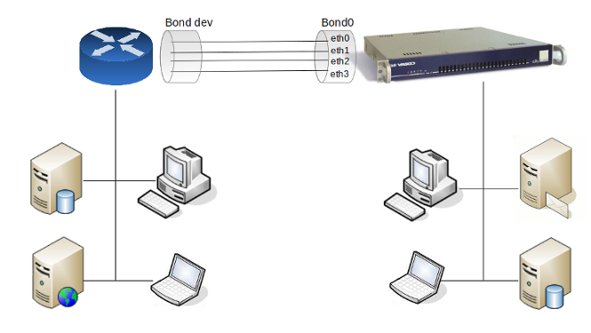
Bonding types Round robin Active backup XOR Balancing 802.3ad Balance TLB Balance ALB Adaptive Transmit Load Balancing Adaptive Load Balancing
Ethernet Bonding Types
The AXS Guard supports the following bonding types:
-
Round Robin: Packets are transmitted in a round robin fashion over the available slave interfaces. This type provides both load balancing and fault tolerance.
-
Active Backup: One slave interface is active at any time. If one interface fails, another interface takes over the MAC address and becomes the active interface. Provides fault tolerance only. Doesn’t require special switch support.
-
XOR Balancing: Tranmissions are balanced across the slave interfaces based on source MAC) XOR (dest MACsource MAC) XOR (dest MAC modula slave count. The same slave is selected for each destination MAC. Provides load balancing and fault tolerance.
-
Broadcast: Transmits everything on all slave interfaces. Provides fault tolerance.
-
802.3ad: This is classic IEEE 802.3ad Dynamic link aggregation. This requires 802.3ad support in the switch and driver support for retrieving the speed and duplex of each slave.
-
Balance TLB: Adaptive Transmit Load Balancing. Incoming traffic is received on the active slave only, outgoing traffic is distributed according to the current load on each slave. Doesn’t require special switch support
-
Balance ALB: Adaptive Load Balancing — provides both transmit load balancing (TLB) and receive load balancing for IPv4 via ARP negotiation. Doesn’t require special switch support, but does require the ability to change the MAC address of a device while it is open.
Configuration
-
Go to Devices > Eth.
-
Select the appropriate logical device, e.g. bond0.
-
Select the interface type (zone).
-
Configure the connection settings, IP address(es) and connectivity check.
-
Select the Bonding Settings tab to configure your bonding device.
-
Update your configuration.
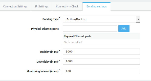
Option / Field |
Description |
|---|---|
Bonding Type |
|
Physical Ethernet Ports |
The Ethernet devices to be aggregated into the bond group, e.g. |
Updelay (in ms) |
If a link has been brought up, the bonding interface is disabled for the duration specified in the updelay time and after this time it is enabled. The value should be a multiple of the MII-interval. |
Downdelay (in ms) |
if a link failure has been detected, the bonding interface is disabled for the duration specified in the downdelay time. This value should be a multiple of the MII-interval |
Monitoring Interval (in ms) |
Specifies the MII link monitoring frequency in milliseconds. This determines how often the link state of each slave is inspected for link failures. A value of zero disables MII link monitoring. A value of 100 is a good starting point. |
Bond policy for load balancing |
Select the appropriate policy from the drop-down list (this option is only available if supported by the selected bonding type).
|
Bridging
Concepts
It is sometimes useful to divide one physical network (such as an Ethernet segment) into two separate network segments without having to create IP subnets and use a router to connect the segments together. A device that connects two networks together in this fashion is called a “bridge”. If your appliance has two or more network interfaces, they can be configured as a bridge.
The bridge works by learning the MAC layer addresses (Ethernet addresses) of the devices on each of its network interfaces. It forwards traffic between two networks only when its source and destination are on different networks.
In many respects, a bridge is like an Ethernet switch with very few ports.
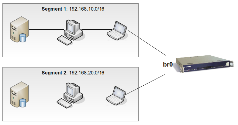
-
Connecting Networks: Joining two or more network segments together. There are many reasons to use a host-based bridge over plain networking equipment such as cabling constraints, firewalling and routing. A bridge can also connect a wireless interface running in hostap mode to a wired network and act as an access point.
-
Filtering/Traffic Shaping Firewall: A common situation is where firewall functionality is needed without routing or network address translation (NAT).
-
Network Tap: A bridge can be used to inspect all Ethernet frames that pass between the connected network segments. This can be achieved with a traffic analyzer such as tcpdump(1) or by sending a copy of all frames to an additional interface (span port).
-
Layer 2 Redundancy: A network can be connected together with multiple links and use the Spanning Tree Protocol to block redundant paths. For an Ethernet network to function properly, only one active path can exist between two devices. Spanning Tree will detect loops and put the redundant links into a blocked state. Should one of the active links fail then the protocol will calculate a different tree and reenable one of the blocked paths to restore connectivity to all points in the network.
The Spanning Tree Protocol
To prevent broadcast storms and other unwanted side effects of looping, Digital Equipment Corporation created the spanning tree protocol (STP), which has been standardized as the 802.1d specification by the Institute of Electrical and Electronic Engineers (IEEE).
Essentially, a spanning tree uses the spanning tree algorithm (STA), which senses that the switch has more than one way to communicate with a node, determines which way is best and blocks out the other path(s). It also keeps track of the other path(s), just in case the primary path is unavailable.
An in-depth explanation of STP is outside the scope of this guide. See the appropriate online resources for additional information and details.
Configuration
-
Go to Devices > Eth.
-
Select the appropriate logical device, e.g. br0.
-
Select the interface type (zone).
-
Configure the connection settings, IP address(es) and connectivity check.
-
Configure your Bridge Settings and update your configuration.
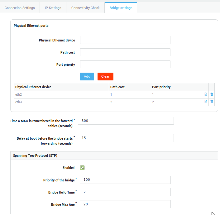
| Parameter | Description |
|---|---|
Physical Ethernet device |
The name of the Ethernet port that you want to add to the bridge. This is the name of the device as listed under Network > Devices > Eth, for example |
Path cost |
A path cost value is given to each port. The cost is typically based on a guideline established as part of the 802.1d standard. According to the original specification, cost is 1,000 Mbps (1 gigabit per second) divided by the bandwidth of the segment connected to the port. Therefore, a 10 Mbps connection would have a cost of (1,000/10) 100. |
Port priority |
The priority value is an unsigned 8-bit quantity (a number between 0 and 255). This metric is used in the designated port and root port selection algorithms. |
Time a MAC is remembered in the forward tables (seconds) |
The factory default value is 300. |
Delay at boot before the bridge starts forwarding (seconds) |
The factory default value is 15. |
To compensate for the speed of networks increasing beyond the gigabit range, the standard cost has been slightly modified. The new cost values are:
| Bandwidth | STP Path Cost Value |
|---|---|
4 Mbps |
250 |
10 Mbps |
100 |
16 Mbps |
62 |
45 Mbps |
39 |
100 Mbps |
19 |
155 Mbps |
14 |
622 Mbps |
6 |
1 Gbps |
4 |
10 Gbps |
2 |
| Parameter | Definition |
|---|---|
Enabled |
Check to enable STP. |
Bridge priority |
The root bridge of the spanning tree is the bridge with the smallest (lowest) bridge ID. Each bridge has a configurable priority number and a MAC Address; the bridge ID contains both numbers combined together - Bridge priority + MAC (32768.0200.0000.1111). The priority value is an unsigned 16-bit quantity (a number between 0 and 65535). Lower priority values are better. The bridge with the lowest priority will be elected root bridge. The bridge priority default is 100. |
Brige Hello Time |
The hello time is the time between each bridge protocol data unit (BPDU) that is sent on a port. This time is equal to 2 seconds (sec) by default, but you can tune the time to be between 1 and 10 sec. |
Bridge Max Age |
The max age timer controls the maximum length of time that passes before a bridge port saves its configuration BPDU information. This time is 20 sec by default, but you can tune the time to be between 6 and 40 sec. |
Firewall Settings
For the bridge to work, you must configure the AXS Guard firewall to
allow traffic between the bridged interfaces. This is done by creating a
"through" rule and adding it to the stat-sec firewall policy. For
details about firewall rules and policies, see the AXS Guard Firewall
How To, which is accessible via the Documentation button in the
administration tool.
In the following example, we assume that you want to allow all traffic
and that the name of the bridge device is br0. The name may be
different on your appliance.
-
Go to Firewall > Rules > Through
-
Click on "Add new"
-
Enter a name for the new rule, e.g. bridge
-
Select your bridge device, e.g.
br0as Device in and Device Out -
Set the protocol to any
-
Save the rule
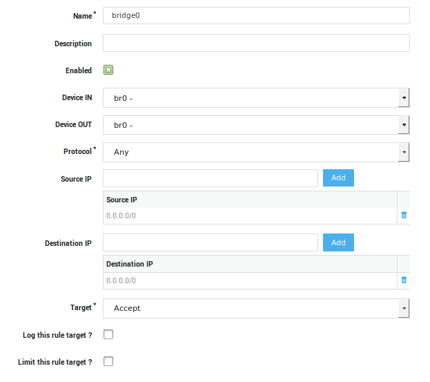
-
Go to Firewall > Policies > Static
-
Select the
stat-secpolicy. -
Click on "Add Firewall Rule"
-
Select the newly created rule
-
Update your configuration
PSTN Devices
Why PSTN devices are used
PSTN devices are used for:
-
communication with an uninterruptible power supply (UPS)
-
HA heartbeat communications
PSTN Configuration
-
Navigate to Network > Devices > PSTN
-
Click on a logical device in the list. A screen similar to the image below appears.
-
Configure the general and interface type settings as explained in the table below.
-
Click on Update.
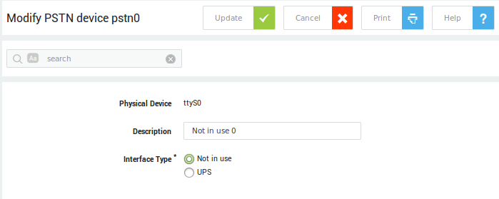
Field |
Description |
|---|---|
Physical Device |
The name of the serial device as seen by the appliance’s operating system, e.g. |
Description |
Enter a description for the device (optional). |
Interface Type |
|
Network Tools
Ping
Ping is a computer network administration software utility used to test the reachability of a host on an Internet Protocol (IP) network.
-
Navigate to Network > Tools > Ping.
-
Enter an IP address or hostname to ping.
-
Enter the amount of pings to execute.
-
Press the Ping button.
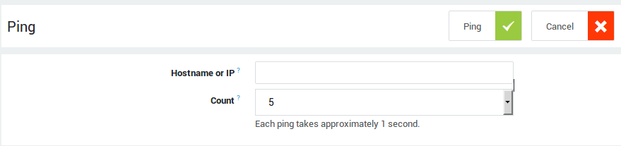
Traceroute
Traceroute is a computer network tool for measuring the route path and transit times of packets across an Internet Protocol (IP) network.
-
Navigate to Network > Tools > Traceroute.
-
Enter an IP address or hostname.
-
Press the Traceroute button.
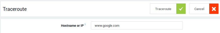
Subnet Calculator
The subnet calculator takes an IP address and netmask (CIDR) and calculates the resulting broadcast, network and host range. It is also intended to be a teaching tool and presents the subnetting results.
-
Navigate to Network > Tools
-
Select the subnet calculator tool
-
Enter the IP address and subnet using the CIDR notation, e.g.
10.20.30.40/24or10.20.30.40/255.255.255.0 -
Click on calculate for the results.
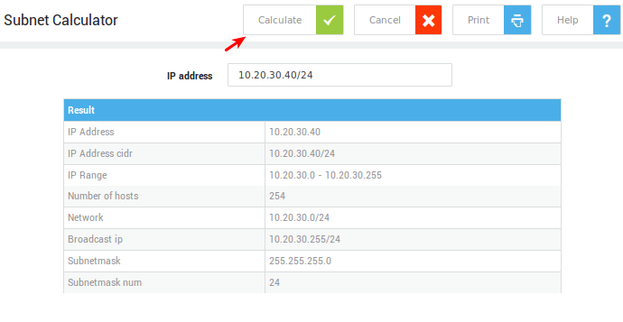
Flow Viewer
The flow viewer allows you to view active connections and use filters to extract information based on the:
-
Protocol
-
Source IP and port
-
Destination IP and port
-
Network device
-
Connections that are monitored by the application control system
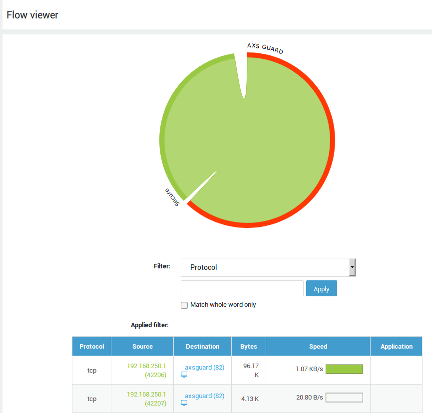
Internet Speed Test
The speed test measures your Internet connection speed in Megabits Per Second, which is the ISP industry standard. Run this test to verify the connection speeds advertised by your ISP.
-
Navigate to Network > Tools > Internet speed test.
-
Click on the Start Speed Test button.
-
Select the desired mode.
-
Press the Start Speed Test button again.
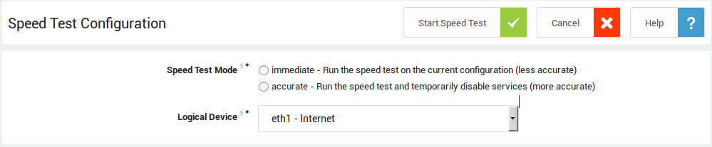
Important
Speed test results may vary between devices, based on network congestion, available bandwidth and the server that was used to perform the test.
AXS Guard will automatically select a server to measure your Internet connection speed. Once a speed test is complete, the results and the server used for the speed test will appear on the Internet speed test history page.
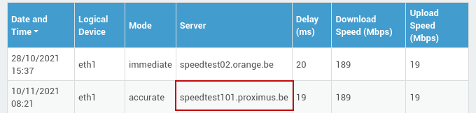
If you run a speed test from a client in your network and your test results are significantly different than the ones produced by AXS Guard, make sure to use the same test server on your client when attempting to compare results.
Example:
- Start your favorite browser on a client PC.
- Go to speedtest.net.
- Change the server to the one used by AXS Guard, e.g.
speedtest101.proximus.be.
Wake on LAN
The Wake on LAN or WoL tool allows a computer or networked device to be remotely powered on from a sleep or powered-off state over a local network or the Internet.
- Navigate to Network > Tools > Wake on LAN.
- Select the appropriate options and enter the MAC address of the host you want to wake up.
-
Click on the Wake Up button.
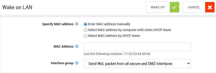
Domain Name Server (DNS)
What is DNS?
The Domain Name System (DNS) is a distributed, hierarchical naming system for computers, services, or any resource connected to the Internet or a private network. It associates various information with domain names assigned to each of the participants. An often used analogy to explain the Domain Name System is that it serves as the "phone book" for the Internet by translating human-friendly computer host names into IP addresses and vice versa.
The protocol used by DNS is an application protocol of the TCP/IP protocol suite. Requests for translations to this system use the UDP and TCP protocols on port 53.
Domain Concept
Domains group networked (sub)structures and use intuitive identifiers (domain suffixes, such as vasco.com). The substructures can either be sub-domains, computers, other hosts, e.g. routers and printers or even services (as illustrated below).
The use of domains (domain names) offers the following advantages:
-
Name Grouping: Names of individual hosts and services used within an organization can be grouped into a single domain (using the same domain suffix) for name to IP address mapping purposes and vice versa. For example, all computers (hosts) within Able have names ending in
vasco.com, e.g. www.vasco.com, mail.vasco.com, etc. -
Intuitive names: An IP address by itself doesn’t represent any characteristics of the host or service. The intuitive naming of a domain and its hosts identifies the purpose and characteristics of a host, such as the country of origin, the name of the company, the service provided by the host, etc. The following information can be deducted from the name mail.vasco.com:
-
The
comsuffix indicates that the server belongs to a company -
Able is the name of the company which owns the server
-
mailindicates that the host is a mail server
-
-
More efficient and reliable name resolution: Without the name grouping concept, no hierarchical resolution of addresses would be possible, meaning all requests for domain name resolution would be directed to one physical place (a single root server on the Internet). This would not only slow down the entire name resolution process, but would also make the Internet less reliable, since there would be no redundant servers to take over if the single root server crashed. The domain concept allows domain names to pin-point a particular address of a host and the resolution of each part of the domain name occurs at different levels and is handled by different DNS (and DNS backup) servers. This distributed system thus improves the speed, reliability and efficiency of the Internet.
Fully Qualified Domain Names (FQDN)
Each host in a network has a Fully Qualified Domain Name (FQDN), which
points to information about that host. This information may include the
IP address(es), information about mail routing, etc. A Fully Qualified
Domain Name is the human-readable name which includes a hostname and its
associated domain name. For example, if you combine the hostname www
and the domain name vasco.com, they form the following FQDN:
www.vasco.com.
Unqualified Domain Names (UQDN)
The Unqualified Domain Name or UQDN is the name of the host without the
domain suffix. For example, www and mail are a UQDNs, vasco.com is
the domain. Joined together they form the following FQDNs:
-
mail.vasco.com
Internal DNS Concepts
The AXS Guard appliance has an internal DNS service and a public DNS service. The internal DNS service, explained in this section, specifically serves the local network, i.e. the secure LAN, VPN clients and the DMZ. It also caches and forwards DNS requests. The public DNS server provides domain name resolution for hosts on the Internet.
The internal DNS automatically collects DNS records. The following information is collected by the AXS Guard’s internal DNS:
-
Names given to network devices, e.g.
axsguard. -
Names given to computers in the LAN.
-
SRV records to enable location of services outside of the standard record types supported in DNS.
-
General names, such as tool, login, logout.
Internal DNS Flow
The AXS Guard’s internal DNS flow is illustrated below.
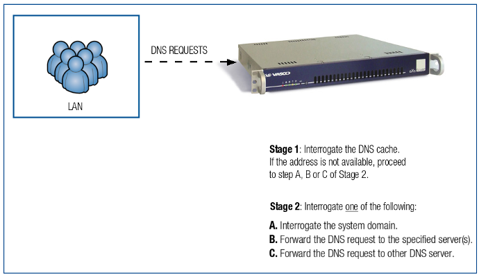
Stage 1: Local Records
When a DNS query is received (e.g. <subdomain>.<systemdomain>), the system first verifies whether the requested hostname matches a record in the local DNS (for example: static DNS entries, registered computers or cached records).
If a matching entry is found:
- The corresponding IP address is immediately returned.
- No further DNS processing is performed.
- The response is sent directly to the client.
Note
This mechanism improves performance, reduces external DNS traffic and minimises lookup latency.
Example: If www.google.com has already been resolved and is available locally, the stored IP address is returned immediately. A new external lookup is not required.
If no matching entry exists, the process continues to Stage 2.
Stage 2: Handling Queries
If the query does not match a local DNS entry, the system evaluates how the request should be processed.
Step 2.1 – Should the query be forwarded?
The system determines whether the requested domain matches a configured forwarding rule.
Forwarded DNS server
If the domain matches a specific forwarding configuration:
- The DNS query is forwarded to the designated DNS server.
- This server resolves the query.
- The response is returned to the client.
Forwarding is typically configured for specific domains that must be resolved by a defined DNS server.

Step 2.2 – Default upstream DNS resolution
If no local record exists and no forwarding rule applies, the query is sent to the default upstream DNS server. Depending on the system configuration under Network > General, this may be:
- A DNS server of an ISP
- SecureDNS
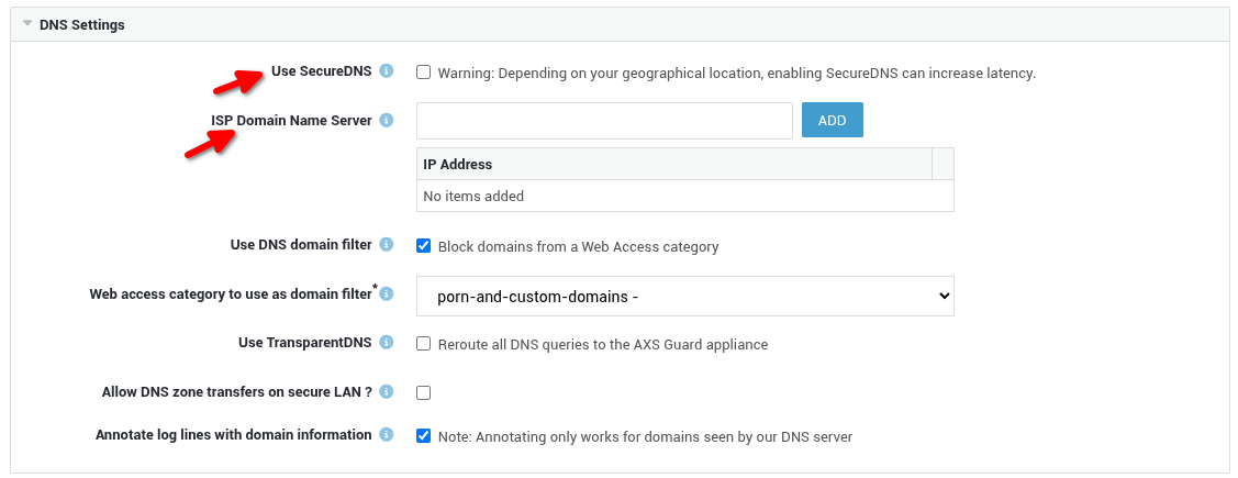
Important
The upstream DNS server performs recursive resolution as required and returns the result.
If no DNS servers are configured, resolution may fall back to root servers, which can negatively impact lookup performance. For optimal performance, upstream DNS servers or SecureDNS should always be configured.
DNS Security
Important
The DNS security feature consists of SecureDNS and DNS filtering. Both can be used independently. These features must be activated before use. DNS filtering requires a comfort threat protection licence or higher. SecureDNS requires a premium threat protection license. See the section about licensing for additional information.
SecureDNS
SecureDNS protects users from inadvertently accessing malware, ransomware, malicious domains, botnet infrastructure and more. It is an essential component of cybersecurity.
Research by industry leaders indicates that more than 91% of malware relies on DNS in one way or another. Despite this, many organizations don’t monitor DNS traffic, leaving them vulnerable to attacks.
SecureDNS leverages threat intelligence services from multiple industry leaders and is capable of blocking millions of threats.
Blocked DNS requests are classified by the type of threat they represent. The reporting feature and DNS security logs can be used to get insights into malicious DNS activity and allow you to easily identify and isolate devices from your network for further investigation and troubleshooting.
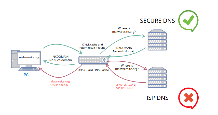
DNS Filters
System administrators have the flexibility to enhance the existing SecureDNS filters by incorporating additional ones according to their specific requirements. It's important to note that the DNS filtering feature can also be used independently, without relying on SecureDNS.
These supplementary DNS filters are built upon web access filter categories, allowing administrators to exert greater control over the network's DNS resolution process. The factory default blacklist provides comprehensive coverage for the majority of DNS security requirements.
By adding DNS filters, administrators can selectively block access to specific websites or categories of websites, helping to enforce content restrictions, enhance security, and ensure compliance with organizational policies, resulting in a safer and more productive browsing experience for users.
Configuration Options
DNS filters can be configured directly on AXS Guard or via the Cyber Resilience Portal. The latter is recommended for large-scale installations.
On AXS Guard
To configure your DNS security settings directly on AXS Guard:
- Log in to your AXS Guard appliance and go to Network => General.
- Configure the options as explained in the table below.
- Save your configuration.
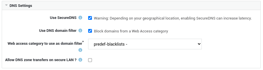
Field |
Description |
|---|---|
Use SecureDNS |
SecureDNS protects users from inadvertently accessing malware, ransomware, malicious domains, botnet infrastructure and more. It is an essential component of cybersecurity. Note that clients must be configured to use AXS Guard as their preferred DNS server. This can be achieved manually by configuring the advanced TCP/IP Settings for each DNS client or automatically through DHCP. Also see the DNS Security Quickstart guide on this site for detailed step-by-step instructions and valuable security recommendations. |
ISP Domain Name Server |
This field is only visible if SecureDNS is not selected. Enter the IP address(es) of your ISP’s DNS servers. |
Use DNS domain filter |
Block additional domains at the DNS level to prevent them from being accessed on user devices. Typical use cases include, but are not limited to, blocking domains related to gambling, NSFW content, phishing, malware and more. This option can be used independently, without relying on SecureDNS. |
Web access category to use as domain filter |
To determine the categories of domains to block at the DNS level, navigate to Web Access > Filters > Categories, where you can create or view the specific category of domains that should be blocked. The factory default blacklist provides comprehensive coverage for the majority of DNS security requirements. Important - DNS Filters vs. Web Access Filters DNS filters, while rooted in established web access filter categories, require a level of granularity for effective blocking. At a minimum, they should incorporate top-level domains (TLDs) and, ideally, second-level domains (SLDs). For instance, merely inputting 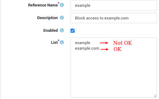
|
Use TransparentDNS |
Redirects all DNS queries to AXS Guard if enabled. Port forwarding rules will be created for UDP & TCP port 53 to intercept all DNS queries originating from secure networks. These queries are then forwarded to the AXS Guard DNS server. This ensures DNS security for all devices, even if they are misconfigured. |
Allow DNS zone transfers on secure LAN ? |
Zone transfers are a system to synchronize data across DNS servers. When data on the primary DNS server is updated, the information will also be updated on the secondary DNS server. Enable to allow zone transfers in the secure LAN.
|
Annotate log lines with domain information |
Annotate DNS information in log messages. Note that this only works if the AXS Guard appliance is used as the primary DNS server. |
Cyber Resilience Portal
To configure DNS filters via the Cyber Resilience Portal:
- Log in to the Cyber Resilience Portal.
-
Select the appropriate context.

-
Go to Adaptive Security > Configuration > Profiles > Management and create a new management profile.
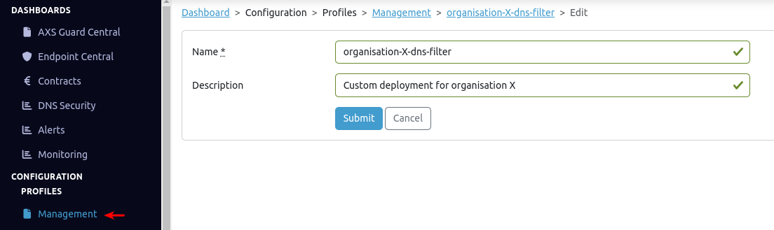
-
Go to Adaptive Security > Configuration > Profiles > Assignment.
-
Search for the appropriate license (for example:
0000-00012345). - Click on the license number (for example:
0000-00012345). - Click the Edit button.
-
Select the profile(s) to be assigned and click the Update button.
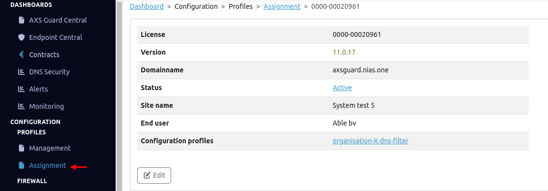
-
Create a new web filter and assign it to the profile created in step 3.
Important
On the AXS Guard appliance, web filters will be referenced by a
cm-e-prefix. -
Log in to your AXS Guard appliance.
- Navigate to Web Access > Filters > Categories.
-
Create a new category and assign the filter created in step 9. Note the
cm-e-prefix in the name of the filter.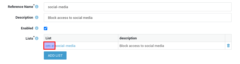
-
Navigate to Nework > General to assign the domain filter.
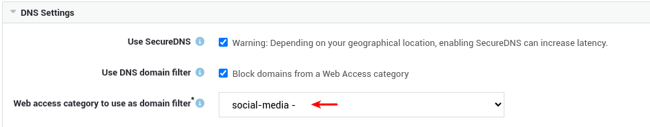
DNS Security Logs & Categories
DNS security logs allow you to get insights into which type of content is being blocked, when it is being blocked and which hosts are affected.
Affected hosts can be identified by their source IP address or hostname, allowing you to isolate them from your network for further investigation and troubleshooting.
- Go to Network > DNS > DNS Security Logs.
- Click on the appropriate date to inspect the logs.
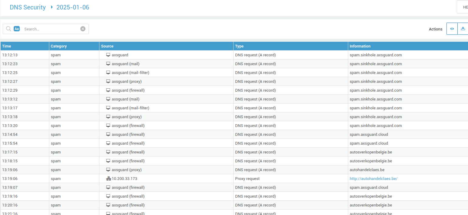
Important
The DNS security logs & network security logs contain valuable information about malicious DNS queries, which are categorized based on the threat they represent. The categories are listed below.
| Categories | Description |
|---|---|
| APT | An Advanced Persistent Threat uses continuous and sophisticated hacking techniques to gain access to a system and remain inside for a prolonged and potentially destructive period of time. This is the most dangerous type of attack. Hits in this bucket must be acted on immediately. |
| Blacklist | Domains that have been examined by Belgian security experts (Secutec) and that have been found malicious (regardless of the category). Those domains typically migrate into another category once they have been verified independently by other security experts. These entries are very up-to-date and might indicate an early serious intrusion attempt. |
| Botnet | A network of private computers infected with malicious software and controlled as a group without the owners' knowledge. Hits in this bucket mean that malicious software is running on the network that tries to reach their “Command & Control” center to receive instructions. These computers should be examined and cleaned immediately as they are in great danger without SecureDNS protection, e.g., a compromised laptop of a home office user who is connecting to corporate HQ. |
| Malware | Typically websites or computers that host malicious software. Hits in this bucket mean that an attempt is made to download and install the malicious software on that host computer. This can occur when a user clicks on a URL in an email/document or when malicious code on a computer tries to obtain additional malicious code to further hack the network. |
| Phishing | Fraudulent websites aiming to steal user credentials. Typically triggered by users that click on URLs in phishing emails or documents. Includes BAPS feeds by Secutec. |
| MalDom | This is an entry bucket of malicious domains where the detailed classification is not yet fully done or where malware was hosted in the past 6 months. After classification, those domains move to either Malware, Phishing, or remain in MalDom. This bucket can also be seen as the gray zone of domains. In theory, it could contain false positives, but in practice, it never happens. |
| Spam | Websites with meaningless content that are not yet fully classified. Most domains end up in either Phishing or Scam. |
| Certs | This bucket contains domains reported by the Computer Emergency Response Teams and can be of any type as long as the classification is not yet done. The most important contributor is the Belgian CERT who processes all reported Cybersecurity incidents in Belgium. |
| Scam | Fraudulent websites like fake webshops. They do not contain malicious software, but they try to get users to buy (and pay) for goods that are never shipped. |
| New domain | Domains seen for the first time within the last 24 hours. These entries are removed or will change to another category as soon as they are classified. Experience shows that phishing and malware sites use those domains in their bulk attacks. For regular domain usage, the limitation of not being able to access it for the first 24 hours is not an issue. |
| Test | Test domains for SecureDNS, e.g. test.sinkhole.axsguard.com. |
| DNS-Filter | Indicates that the query was blocked by an additional DNS filter based on a web access filter category. |
| Uncategorized | Domains that do not fall into any of the listed categories. |
Internal DNS Zone Transfers a.k.a. Secondary DNS
A backup DNS server, also known as a Secondary DNS server, handles DNS queries if the Primary DNS server is being rebooted or fails. Zone transfers enable the synchronization of data between the AXS Guard DNS server and secondary DNS servers in your LAN. When the DNS repository of the AXS Guard is updated, the repository of the secondary DNS server (and any additional configured DNS servers) is updated as well.
Examples of Internal DNS Setups
With Microsoft Active Directory Domain
DNS queries for the domain specified on the Active Directory (AD) Server are handled by the AD server, while queries for other domains are handled by AXS Guard. The DNS queries for other domains are forwarded to the AXS Guard appliance by the AD server, hereby shielding the secure LAN. The setup is illustrated below.
Enter the IP addresses of your ISP’s DNS servers or use SecureDNS. This optimizes DNS queries towards the Internet. If no addresses or DNS options are configured, AXS Guard will use the Internet Root DNS servers.
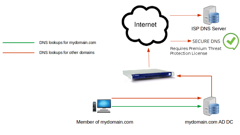
Without Microsoft Active Directory Domain
DNS queries for the domain specified on the AXS Guard appliance are handled by AXS Guard, while requests for other domains are handled by the ISP’s DNS servers or SecureDNS. The setup is illustrated below.
Enter the IP addresses of your ISP’s DNS servers or use SecureDNS. This optimizes DNS queries towards the Internet. If no addresses or DNS options are configured, AXS Guard will use the Internet Root DNS servers.
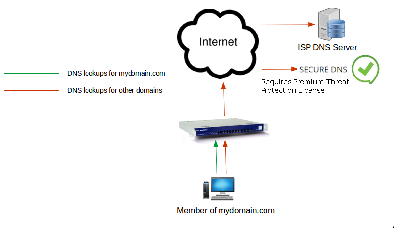
With a Secondary DNS Server (DNS Zone Transfers)
All DNS requests are forwarded to the AXS Guard appliance, which is the Primary DNS server. The DNS zones are transferred to a secondary (backup) DNS server. The backup DNS server will temporarily handle all internal DNS queries if the AXS Guard appliance is rebooted for maintenance. This setup is illustrated below.
Enter the IP addresses of your ISP’s DNS servers or use SecureDNS. This optimizes DNS queries towards the Internet. If no addresses or DNS options are configured, AXS Guard will use the Internet Root DNS servers.
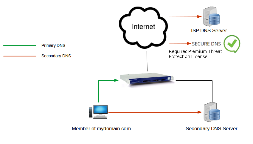
AXS Guard as an Authentication Server with Active Directory DNS
In this scenario, DNS queries for the corporate domain are handled by the Active Directory (AD) Server. DNS queries for other domains are forwarded to the DNS server configured on the Active Directory server. In the example below, the AXS Guard appliance is set up as a standalone authentication appliance; its DNS features aren't used.
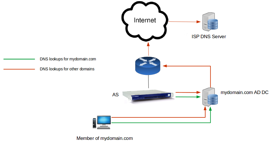
DNS Forwarding
DNS forwarding is the process by which particular sets of DNS queries are handled by a designated server, rather than being handled by the initial server contacted by the client.
-
Go to Network > DNS > Forwarding.
-
Configure the settings as explained in the table below.
-
Click on Save to finish.
| Field | Description |
|---|---|
Forward Requests for Domain |
Enter the forward or reverse lookup zone for which DNS queries should be forwarded, e.g.
|
Description |
Provide a description (optional field). |
Enabled |
Check to enable forwarding for the specified zone. |
Forward to DNS server(s) |
Enter the IP address(es) of the DNS server(s) to which queries for the specified zone must be forwarded. |
Public DNS
The public DNS server provides domain name resolution for hosts on the Internet. For more information on the use and configuration of the AXS Guard’s public DNS server, see the AXS Guard Public DNS How To, which can be downloaded via the Documentation button in the configuration tool.
Dynamic DNS
Dynamic DNS or DDNS allows you to assign a static hostname to a device with a dynamic IP address. This simplifies remote access, enabling users to connect to external AXS Guard services (e.g., VPN) by using a user-friendly hostname instead of tracking a changing IP address or hostname. To use this feature, you need to register with a supported Dynamic DNS provider and activate it on the AXS Guard system.
-
Log in to AXS Guard.
-
Navigate to System > Feature Activation.
-
Enable the Dynamic DNS option under Network.
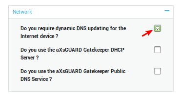
-
Navigate to Network > DNS > Dynamic DNS
-
Enter the account settings as provided by your Dynamic DNS provider.
-
Configure the remaining options as explained in the table below.
-
Update your configuration.
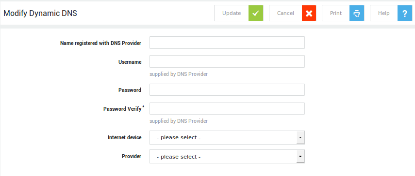
| Parameter | Description |
|---|---|
Name registered with DNS Provider |
The full name, including the domain, as registered with your Dynamic DNS Provider, e.g. |
Username |
Enter the username of your DDNS account. |
Password |
Enter the password of your DDNS account. |
Use IP address of internet device? |
This option is disabled by default.
|
Internet device |
Select the Internet device that will be handling traffic for the domain, e.g. |
Provider |
Select the appropriate DDNS provider from the drop-down list. |
DHCP
What is DHCP?
The Dynamic Host Configuration Protocol (DHCP) is an application protocol that enables your appliance to dynamically assign IP addresses to computers and other devices in its network.
DHCP simplifies network administration because software automatically keeps track of IP addresses so that administrators don’t have to. Many Internet Service Providers (ISPs) use DHCP to assign IP addresses to their clients.
A DHCP lease is the amount of time during which the DHCP client may use an assigned IP address. The AXS Guard DHCP server allows you to configure the lease time.
Data received from the DHCP Server
A computer connecting to the network receives the following parameters from the AXS Guard DHCP server:
-
an Internet Protocol (IP) address
-
a default gateway address
-
one or more Domain Name Server (DNS) address(es)
-
a Windows Internet Name Server (WINS) address, if present in your network
-
a Network Time Protocol (NTP) server address
Address Pools
An address pool or DHCP range is a range of valid IP addresses made available for assignment to clients in a particular subnet. Address pools are configured on the AXS Guard DHCP server. IP addresses from this pool are then offered by the AXS Guard to DHCP clients.
Addresses are offered by an AXS Guard network interface. This can be a DMZ or a secure LAN interface.
The AXS Guard also allows you to reserve IP addresses for dedicated hosts, e.g. dedicated servers and printers. Such leases are referred to as static leases.
Attempts to create invalid pools will generate a validation message.
Static Leases
Use static IP addresses rather than static DHCP leases for the Windows Servers in your network. Windows Servers may malfunction if the AXS Guard’s DHCP lease settings are changed.
With a static DHCP lease, the AXS Guard’s DHCP server always assigns the same IP address to a specific host in the LAN. Static DHCP leases allow:
-
Automatic assignment of static IP addresses to servers and central management of the IP addresses.
-
Settings which are defined in the configured DHCP range (e.g. DNS servers) can be overruled. This is required for certain programs to function properly.
Authoritative vs. Not Authoritative
The DHCP server will normally assume that the configuration information about a given network segment is not known to be correct and is not authoritative. This is so that if a naive user installs a DHCP server not fully understanding how to configure it, it does not send spurious DHCPNAK messages to clients that have obtained addresses from a legitimate DHCP server on the network.
Network administrators setting up authoritative DHCP servers for their networks should always enable the authoritative option to indicate that the DHCP server should send DHCPNAK messages to misconfigured clients. If this is not done, clients will be unable to get a correct IP address after changing subnets until their old lease has expired, which could take quite a long time.
PXE Options
If you’re looking to perform a lot of system recovery or network system installations, then network booting with PXE is ideal. PXE allows you to boot up a system and have it automatically get an IP address via DHCP and start booting a kernel over the network.
PXE itself stands for "Pre-boot eXecution Environment", which describes how it works in the sense that the clients using it do not boot in a traditional manner.
In order to use PXE, you need to setup a boot server which will allow client systems to:
-
Request an IP address (via DHCP)
-
Download a kernel (via TFTP or next-server)
With both of these services in place, any system which supports PXE/network-booting (you might need to enable it in the BIOS) should be able to get an IP address, fetch a kernel, and boot without an installed operating system. This is ideal for systems which can’t be booted using a traditional approach, e.g. VoIP phones.
DHCP Relay Agents
About
A DHCP relay agent is a small program (often running on a router or server) that relays DHCP/BOOTP messages between clients and servers on different subnets. DHCP/BOOTP relay agents are defined in the DHCP and BOOTP standards (RFC 2131, RFC 951) and are used because broadcast messages from DHCP clients cannot cross router boundaries.
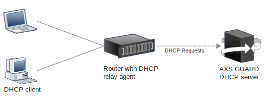
DHCP Relay Agent Flow:
- A DHCP client broadcasts a DHCPDISCOVER message to find an IP address.
- A DHCP/BOOTP relay agent (typically a router) receives this broadcast and sets its own IP address in the
giaddr(gateway IP address) field of the DHCP message. - The relay agent then forwards the message as a unicast packet to the configured DHCP server.
- The DHCP server processes the request and sends a DHCPOFFER to the relay agent's IP address (the
giaddr). - The relay agent then forwards the DHCPOFFER to the client, typically as a broadcast.
Configuration
Feature Activation
- Log in to your AXS Guard appliance.
- Go to System > Feature Activation and select the Network tab.
-
Enable the DHCP Relay feature.
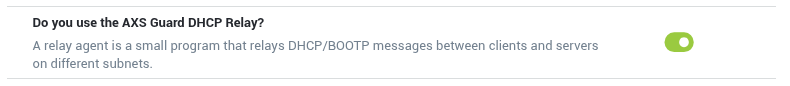
Adding a DHCP Relay Agent
- Log in to your AXS Guard appliance.
- Go to Network > DHCP Relay > Agents.
- Click on the
+button to add a new configuration. - Enter the settings as explained in the table below.
-
Save your configuration.
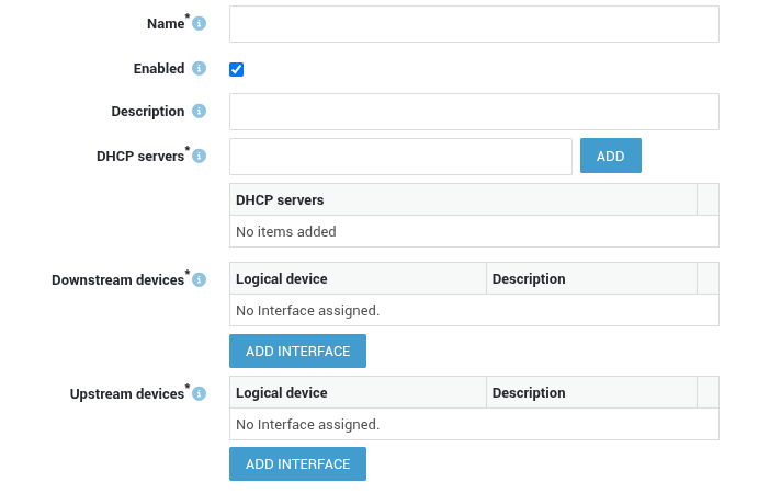
| Name | Description |
|---|---|
| Name | Enter a unique name for the agent, e.g., department_x. |
| Enabled | Check to enable the relay agent. |
| Description | Enter a description that provides extra contextual information. Descriptions are optional, but useful if you have multiple DHCP relay agents to manage. The description will also appear in the overview. |
| DHCP servers | Add one or multiple IP addresses of DHCP servers to which DHCP requests should be relayed. |
| Downstream devices | Select the network interfaces the agent should listen on for incoming DHCP requests. |
| Downstream etunnel | Select the etunnel the agent should listen on for incoming DHCP requests. |
| Upstream devices | Select the network interfaces that connect to the DHCP server(s). The selected devices will be used to forward DHCP requests and receive DHCP responses. |
| Upstream etunnel | Select the etunnel that connects to the DHCP server(s). The selected tunnel will be used to forward DHCP requests and receive DHCP responses. |
Logs
- Log in to your AXS Guard appliance.
- Go to Network > DHCP Relay > Logs.
-
Select the appropriate log date to view its entries.
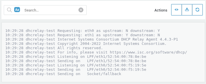
DHCP Server Configuration
Enabling DHCP
Important
Using multiple DHCP servers in a subnet causes conflicts.
-
Navigate to System > Feature Activation > Network
-
Check the option to use the DHCP Server (see the image below)
-
Click on Update to finish
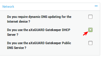
Adding an Address Pool
-
Navigate to Network > DHCP > Address Pools
-
Click on the Add New button to add a DHCP pool to a network device (Secure LAN or DMZ).
-
Configure the options as explained in the tables below .
-
Click on Save to finish.
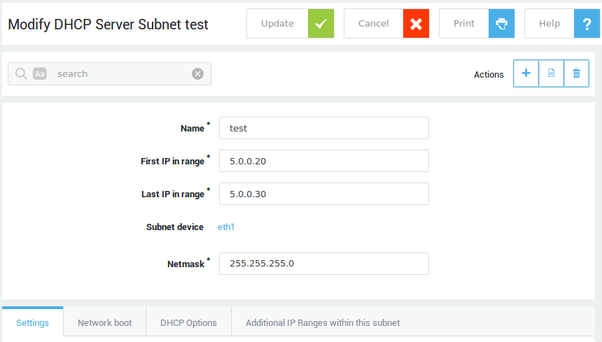
Address Pool Settings
| Field | Description |
|---|---|
Name |
Enter a name for the IP range, e.g. LAN. |
First IP in range |
The first IP address to be issued in the DHCP range, e.g. |
Last IP in range |
The last IP address to be issued in the DHCP range, e.g. |
Subnet device |
The network device that issues IP addresses to clients. Go to Network > Devices > Eth for an overview of network devices on your system. |
Netmask |
The subnet mask to be assigned to clients, e.g. |
Info
Static leases are excluded from configured DHCP ranges.
DHCP Settings
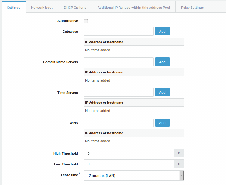
| Field | Description |
|---|---|
Authoritative |
If disabled, misconfigured clients which connect to another AXS Guard subnet will be unable to get a new IP address until their old DHCP lease has expired, which may be quite a long time. If enabled, the DHCP server should send DHCPNAK messages to misconfigured clients, which will receive a new IP address without delays. See http://linux.die.net/man/5/dhcpd.conf for additional information. |
Gateways |
The FQDN or the IP address of the default gateway in your network, e.g. |
Domain Name Servers |
The primary DNS server to be used by your clients. Multiple DNS servers can be added. |
Time Servers |
The FQDN or the IP address of a Time Server, e.g. |
WINS |
The IP address(es) of (a) WINS server(s) in your network. WINS (Windows Internet Name Server) is Microsoft’s implementation of the NetBIOS Name Service (NBNS), a name server and service for NetBIOS computer names. WINS is to NetBIOS names what DNS is to domain names, a central mapping of host names to network addresses. |
High Threshold |
Determines the percentage of available leases to be used prior to sending a system notification. When the threshold is reached, a system warning will be shown on the dashboard and the administrator will be notified by email. Setting the percentage to |
Low Threshold |
If the amount of used leases drops below this threshold, the dashboard system warning message will disappear. |
Lease time |
The maximum duration of DHCP leases. When expired, clients must renew their lease. |
DHCP Settings Tab
Network Boot Settings
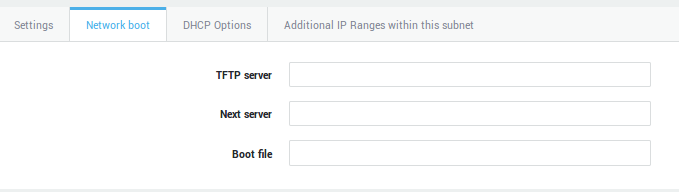
| Field | Description |
|---|---|
TFTP Server |
IP address of a TFTP server to support network booting (PXE), e.g. for VoIP phones or OS installations. |
Next Server |
IP address of a Next server to support network booting (PXE), e.g. for VoIP phones or OS installations. |
Boot file |
Name of the file to be loaded by clients when booting from the network. |
Non-Standard and Vendor-specific DHCP Options
These options are to be used if certain DHCP hardware or software clients in your network expect DHCP options that are not available otherwise. Consult the documentation of your hardware or software clients to know the values that are expected for each option.
The following values are accepted:
-
an IP address
-
text (string)
-
a hexadecimal value
-
a domain name
A list of standard DHCP options can be found here.
RFC2132 provides a list of the most frequently used DHCP options.
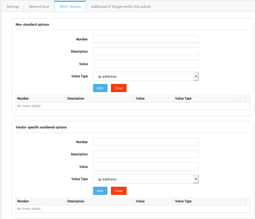
Example: Vendor-specific options to create a PXE boot menu
Vendor-specific numbered option:
-
Number = 6
-
Description = multicast
-
Value type = text
-
Value = 7
Value 7 means: use PXE_BOOT_SERVERS list + disable multicast and broadcast discovery.
-
Number = 8
-
Description = Boot servers
-
Value type = hex
-
Value = 80:F0:01:C0:A8:01:04:80:F1:01:C0:A8:01:05
Option 8 defines the two PXE servers. The first server is defined by the first 7 bytes, starting with the OS deployment server type (80:F0,33008), followed by one IP address: C0:A8:01:04 (192.168.1.4). The second server is defined in the following manner, using OS deployment server type 80:F1 (33009).
-
Number = 9
-
Description = boot menu
-
Value type = hex
-
Value = 80:F0:08:53:65:72:76:65:82:20:41:80:F1:08:53:65:72:76:65:82:20:42
Option 9 defines the boot menu that is displayed at boot time. The first 11 bytes correspond to the first line, for the first server. It shows the string Server A, associated with type 80:F0 (first server). The second line shows the string Server B, associated with type 80:F1 (second server).
-
Number = 10
-
Description = timeout+prompt
-
Value type = hex
-
Value = 0F:53:65:6C:65:63:74
Option 10 specifies a 15 second timeout and shows the string "Select" as the boot menu prompt.
Additional IP Ranges
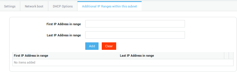
| Field | Description |
|---|---|
First IP address in range |
Enter the first IP address of the additional range, e.g. |
Last IP address in range |
Enter the last IP address of the additional range, e.g. |
| Field | Description |
|---|---|
Authoritative |
If disabled, misconfigured clients which connect to another AXS Guard subnet will be unable to get a new IP address until their old DHCP lease has expired, which may be quite a long time. If enabled, the DHCP server should send DHCPNAK messages to misconfigured clients, which will receive a new IP address without delays. See http://linux.die.net/man/5/dhcpd.conf for additional information. |
Gateways |
The FQDN or the IP address of the default gateway in your network, e.g. |
Domain Name Servers |
The primary DNS server to be used by your clients. Multiple DNS servers can be added. |
Time Servers |
The FQDN or the IP address of a Time Server, e.g. |
WINS |
The IP address(es) of (a) WINS server(s) in your network. WINS (Windows Internet Name Server) is Microsoft’s implementation of the NetBIOS Name Service (NBNS), a name server and service for NetBIOS computer names. WINS is to NetBIOS names what DNS is to domain names, a central mapping of host names to network addresses. |
High Threshold |
Determines the percentage of available leases to be used prior to sending a system notification. When the threshold is reached, a system warning will be shown on the dashboard and the administrator will be notified by email. Setting the percentage to |
Low Threshold |
If the amount of used leases drops below this threshold, the dashboard system warning message will disappear. |
Lease time |
The maximum duration of DHCP leases. When expired, clients must renew their lease. |
DHCP Relay Settings
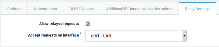
| Field | Description |
|---|---|
Allow relayed requests |
Check to allow relayed requests from a DHCP agent. |
Accept requests on interface |
Accept relayed DHCP requests on the specified interface. |
Static Lease Management
-
Navigate to Network > DHCP > Static Leases. A list of the hosts with static leases is shown.
-
Click on the Add New button to add a new lease or click on a name to modify an existing static lease.
-
Configure the settings as explained in the table below.
-
Click on Save to finish.
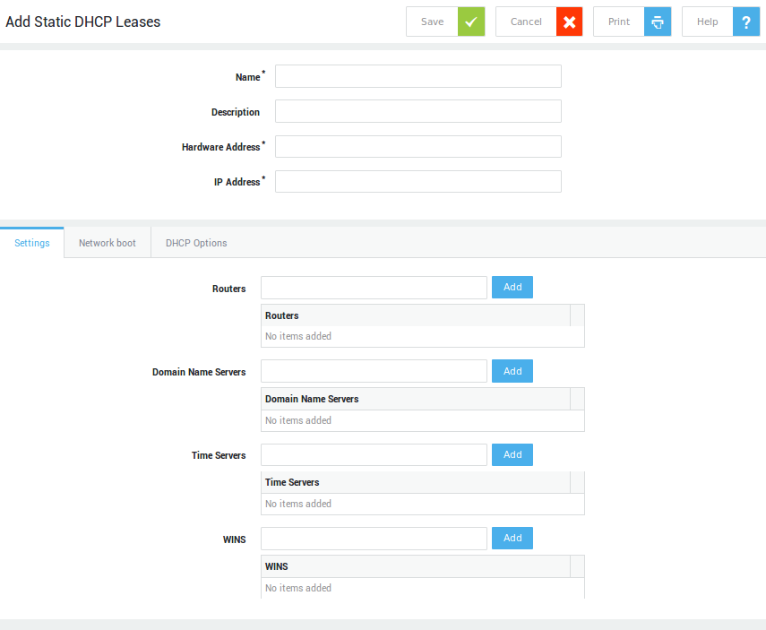
| Field | Description |
|---|---|
Name |
Enter the name of the host to be assigned a static lease. |
Description |
Description of the host (optional), e.g. file server 1. |
Hardware Address |
The host’s MAC address, for instance |
IP Address |
The IP address to be assigned to the host, e.g. |
| Field | Description |
|---|---|
TFTP Server |
IP address of a TFTP server to support network booting (PXE), e.g. for VoIP phones or OS installations. |
Next Server |
IP address of a Next server to support network booting (PXE), e.g. for VoIP phones or OS installations. |
Boot file |
Name of the file to be loaded by clients when booting from the network. |
Non-Standard and Vendor-specific DHCP Options
These options are to be used if certain DHCP hardware or software clients in your network expect DHCP options that are not available otherwise. Consult the documentation of your hardware or software clients to know the values that are expected for each option.
The following values are accepted:
-
an IP address
-
text (string)
-
a hexadecimal value
-
a domain name
A list of standard DHCP options can be found here.
RFC2132 provides a list of the most frequently used DHCP options.
Status & Logging
Used Leases
Navigate to Network > DHCP Server > Used Leases. The fields are explained in the table below.
| Field | Description |
|---|---|
IP |
The IP address which has been assigned within a specified IP range. |
MAC |
The MAC address of the client that received (or currently has) a dynamically assigned IP address. |
Hostname |
The hostname of the DHCP client. |
Expires |
Indicates when the DHCP lease expires. |
Actions |
Clicking on the |
Info
Clients with a static DHCP lease are not listed.
DHCP Logs
-
Go to Network > DHCP > Logs.
-
Click on the appropriate date to view the DHCP logs.
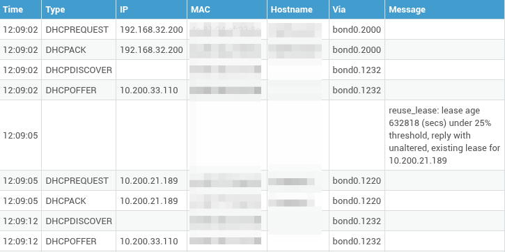
Routing
What is Routing?
Routing is the decision process by which packets are moved from one network to another. Entries in routing tables specify the interface or gateway through which a packet must leave a network to reach another.
Routing tables are processed from the top entry down to the final entry. Whether an IP packet can be sent directly to its destination (communicating with a computer in the same LAN or subnet) or needs to be sent to the computer’s default gateway (attempting to communicate with a computer in another network segment or subnet) is first checked by the sending host. The AXS Guard uses the same principle to send and receive network packets.
Routing Table Entries
The main information recorded in a routing table is explained below.
-
Destination: This is the destination network of a packet. The destination is required to match the packet with an entry in the routing table, for instance
192.168.3.0. -
Netmask: This entry, for instance
255.255.255.0, is checked against the destination entries in the routing table. Netmasking is defined per RFC 950. -
Gateway: This entry designates a specific host (by its IP address) to which packets should be forwarded if the destination address cannot be reached directly by the AXS Guard.
-
Interface / Device: This field specifies the network interface through which a packet destined for a specific network - which can be reached directly by the AXS Guard - must be sent, e.g.
eth0.
Default Gateway
Arriving network packets always traverse the routing table. If the destination network is within reach of one of the AXS Guard network interfaces (i.e. it is a subnet of the AXS Guard), routing entries are automatically added by the AXS Guard and the packets are delivered.
If the destination network cannot be reached directly by the AXS Guard (i.e. it is not a subnet of the AXS Guard), the routing system looks for a matching entry in the routing table. If a matching entry is found in the routing table, the network packets are delivered to the specified gateway for the destination network. If no matching entry is found for the destination network, the network packets are delivered to the default gateway. The routing system discards packets if no gateway or default gateway is specified in the routing table. In this case, a message is generated notifying the sending application that the destination network is unreachable, e.g. if pinging a host which is unreachable.
Most systems using TCP/IP have a routing table entry in which the default gateway is specified.
How Routing Works
What follows is a simple, yet straightforward example of how routing works.
| Case | Destination | Netmask | Gateway | Network Interface |
|---|---|---|---|---|
1 |
192.168.1.1 |
255.255.255.0 |
* |
eth0 |
1 |
192.168.2.50 |
255.255.255.0 |
* |
eth1 |
2 |
192.168.3.50 |
255.255.255.0 |
192.168.2.2 |
eth1 |
3 |
Default GW |
0.0.0.0 |
213.49.50.75 |
eth2 |
Example of basic Routing Table Entries
Case 1
If the network packet is destined for a network which can be reached
directly by the AXS Guard (i.e. for a subnet of the AXS Guard), the
packet is immediately delivered to this network, e.g. a packet traveling
from 192.168.1.50 towards 192.168.2.50 (see the image below).
Case 2
If the network packet is destined for a network which cannot be reached
directly by the AXS Guard, the packet is sent to the gateway of this
network, if specified in the routing table, e.g. a packet traveling from
192.168.1.50 towards 192.168.3.50 (see the image below).
Case 3
If there is no specific gateway routing entry in the routing table for
the destination network, the packet is sent to the default gateway, for
instance a packet traveling from 192.168.1.50 towards www.vasco.com
(see the image below).
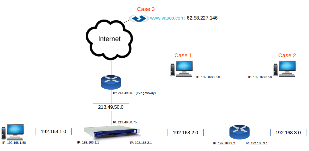
Adding Routes
-
Navigate to Network > Routing.
-
Click on the
+button to add a new route. -
Configure the route using the settings as explained in the table below.
-
Save your configuration.
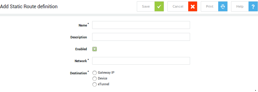
Field |
Description |
|---|---|
Name |
Enter an identifier for the route, using only lower cases without spaces, starting with an alphabetic character followed by any number of alphanumeric characters and/or the special characters: back slash |
Description |
A description for the route (optional), e.g. |
Enabled |
Check to enable the defined route. |
Network |
Enter the destination network, using the CIDR notation, e.g. |
Destination |
|
Consulting the Route Table
When a route has been added to the AXS Guard’s route table and enabled, it can be viewed. To view the main routing table:
Navigate to Network > Status > Route Table.
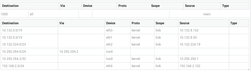
In this section we have described the main routing table. Other routing tables exist, but are outside the scope of this guide.
Network Address Translation
NAT only needs to be configured if the AXS Guard is used as a router or a gateway. If you are using the AXS Guard solely as an authentication appliance, configuring NAT is not necessary and this section may be skipped.
What is NAT?
While network packets travel from a source to a destination, routers which use NAT (Network Address Translation) alter the source or destination headers of the IP packets. If the UDP or TCP protocol is used, the source or destination port can also be altered.
Five NAT types can be configured on the AXS Guard. The types are defined based on the altered header information:
-
Masquerading
-
SNAT (Source Network Address Translation)
-
Port Forwarding
-
DNAT (Destination Network Address Translation)
-
Port Redirection
Masquerading
How Masquerading Works
IP Masquerading, also called IPMASQ or MASQ, allows computers in your network to communicate with the Internet using the IP address of your appliance (the IPMASQ server). The IPMASQ server acts as a gateway and the other devices are invisible behind it. So to other machines on the Internet, the outgoing traffic appears to be coming from the IPMASQ server and not the internal PCs.
In addition to masquerading a packet’s source IP address, the AXS Guard also automatically masquerades source ports, if a port is already in use. The automatic mapping mechanism on the AXS Guard stores the data accordingly so that reply packets are correctly handled (demasqueraded).
Info
Port numbers are assigned based on those which are already in use. The range of available port numbers is pre-configured on the AXS Guard and cannot be changed.
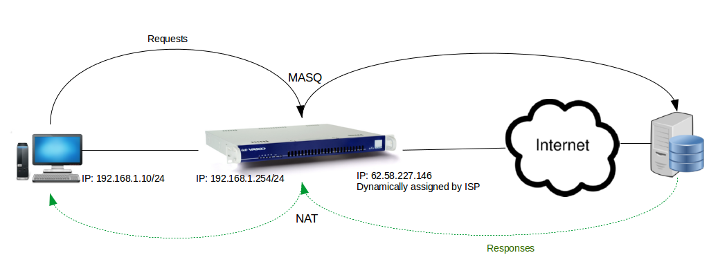
The illustration above shows that all computers in the LAN connect to the Internet via the same AXS Guard Internet connection. The computers in the LAN have a private IP address in the 192.168.1.0/24 segment.
PC1 sends a packet to the outside world (the Internet). The source IP address of this packet is 192.168.1.10, which is an IP address in the private range. Since IP addresses in the private range cannot be routed on the Internet, the Private IP address is masqueraded to the public IP address of the AXS Guard, 62.58.227.146, so that a response can be given by the receiving computer.
Receiving computers reply to 62.58.227.146, which is the AXS Guard. Once the answer is received by the AXS Guard ,the address is rewritten (demasquerading) to 192.168.1.10, which is the address of the sending host.
In the illustration above, we assume that the PC with IP 192.168.1.10/24 makes a connection with an external Web server using source port 2000, which is chosen randomly. The source IP address is 192.168.1.10 and the destination is port 80 (i.e. a connection to a Web server). The AXS Guard masquerades the private source IP address with its Internet interface IP address, which is 62.58.227.146. The source port remains unchanged. The Web server identifies an incoming connection from source IP address 62.58.227.146, with source port 2000 and responds accordingly. When the response is received, the AXS Guard automatically rewrites (demasquerades) the reply packet so that it contains the private source IP address of PC1, i.e. 192.168.1.10, leaving the port (2000) unchanged.
Assume that another PC in the same network simultaneously connects to the same Web server and also uses source port 2000. The AXS Guard identifies an incoming packet with source IP address 192.168.1.20, using port 2000. Since port 2000 is already in use for PC1, both the source IP address and port number need to be automatically masqueraded to allow demasquerading.
Packets sent by the other PC are therefore masqueraded by the AXS Guard to source IP address 62.58.227.146, using a different source port, e.g. source port 2500. The automatic mapping mechanism on the AXS Guard stores the data accordingly so that reply packets are correctly handled (demasqueraded).
Pre-defined Masquerading
Important
When using IP addresses in the private range for hosts in the DMZ, Masquerading rules must be configured on the AXS Guard to enable traffic from the DMZ towards the Internet.
The AXS Guard applies pre-defined masquerading in the following order by default:
| In Interface | Out Interface | Masquerading applied? |
|---|---|---|
DMZ |
Internet |
No |
Secure LAN |
DMZ |
Yes |
Secure LAN |
Internet |
Yes |
If none of the above combinations match, the packet is either:
-
not masqueraded
-
blocked by the firewall
| From | To | Action |
|---|---|---|
LAN |
LAN |
ACCEPT |
LAN |
DMZ |
MASQ |
LAN |
Internet |
MASQ |
DMZ |
LAN |
DROP |
DMZ |
DMZ |
ACCEPT |
DMZ |
Internet |
ACCEPT only if DMZ has public IP |
Internet |
LAN |
DROP |
Internet |
DMZ |
ACCEPT |
Internet |
Internet |
DROP |
In some situations, the predefined masquerading rules do not suffice. If IP addresses in the private range are used for hosts in the DMZ. packets sent from the DMZ to the Internet are discarded if no masquerading is applied. IP addresses in the private range cannot be routed on the Internet. The problem can be solved by adding an explicit masquerade rule for subnets in the DMZ.
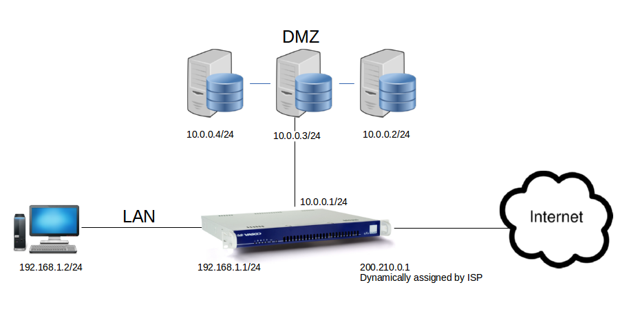
Assume that your DMZ falls in the following private range: 10.0.0.0/24.
Packets sent to the Internet from the DMZ are not masqueraded by default, e.g. packets originating from the server with IP 10.0.0.4/24. If masquerading is not applied to the 10.0.0.0/24 network, all packets sent to the Internet will be discarded.
Creating Masquerading Rules
-
Navigate to Network > NAT > Masquerading
-
Click on the Add New button.
-
Configure the settings as explained in the table below.
-
Click on Save to finish.
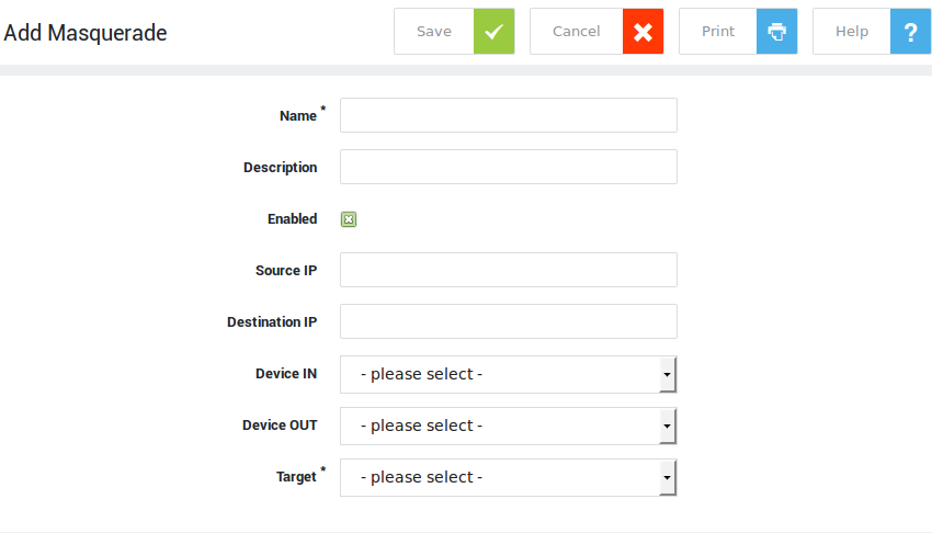
| Field | Description |
|---|---|
Name |
Enter an identifier for the rule, using only lower cases without spaces, starting with an alphabetic character, followed by any number of alphanumeric characters and/or the special characters: back slash |
Description |
Enter a description for the rule, e.g. |
Enabled |
Check to enable the rule. |
Source IP |
The IP range to be masqueraded. Use the CIDR notation, e.g. |
Destination IP |
Enter an IP or subnet to restrict matching to specific destination(s). Use the CIDR notation to specify a subnet. If left blank, the rule applies to any destination IP. |
Device In |
The device that receives traffic to be masqueraded. |
Device Out |
The device that forwards the NATed traffic to other networks. |
Target |
Select the action for matching traffic. "Accept" means that matching traffic should not be MASQed. Select "MASQ" to apply masquerading. |
Source Network Address Translation
How SNAT Works
Source Network Address Translation (SNAT) is a type of NAT that changes the source IP address of packets. Unlike masquerading, the public IP address is not looked up for new connections.
The public source IP must be static for all future connections; SNAT cannot be used with dynamically assigned public IP addresses. Similar to masquerading, the reverse “de-SNAT” process is automatic.
Creating SNAT Rules
-
Navigate to Network > NAT > SNAT & DNAT.
-
Click on the Add New button.
-
Configure the settings as explained in the table below.
-
Click on Save to finish.
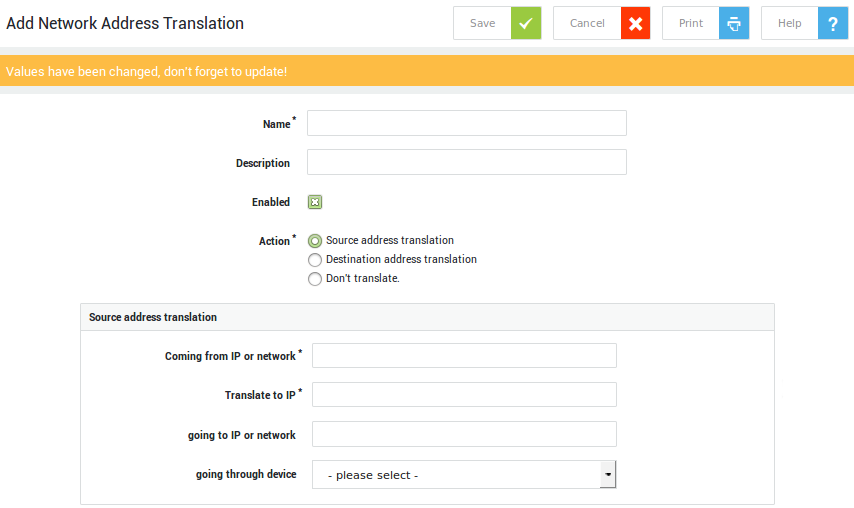
Field |
Description |
|---|---|
Name |
Enter an identifier for the rule, using only lower case without spaces, starting with an alphabetic character, followed by any number of alphanumeric characters and/or the special characters: back slash |
Description |
Enter a description for the rule, e.g. |
Enabled |
Check to enable the rule. |
Action |
|
Source address translation-specific settings |
|
Destination address translation-specific settings |
|
Don’t translate options |
See the options explained above. |
Important
- Sometimes you may need a one-to-one NAT of a network range. For example, you have the 192.168.1.0/24 network and you would like to NAT each IP to its equivalent in 192.168.2.0/24 (SNAT) or vice versa (DNAT) when the packet travels through the NAT device. Make sure the subnets do not overlap each other.
- Select
Don't Translatein the Action field if you wish to define exceptions.
Port Forwarding
About
Port forwarding is a type of NAT that is used to change the destination IP address and/or the destination port of network traffic.
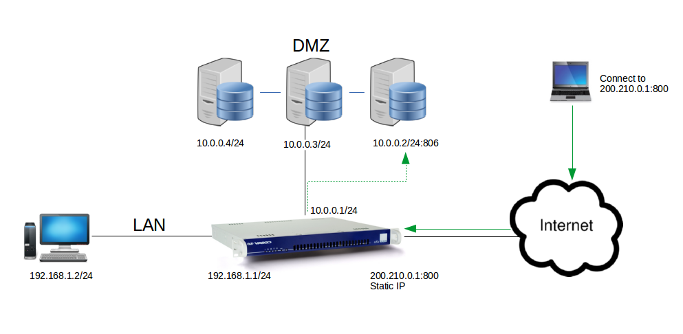
Port forwarding can be used to forward incoming traffic on the AXS Guard to a server in the DMZ (configured with a private IP address). Whenever a connection is made from the Internet to the Internet IP address of the AXS Guard, the connection can be forwarded to a server in the DMZ listening on a different port.
Based on the image above, a connection to 200.210.0.1 on port 800, is forwarded to 10.0.0.2 on port 806. The server receives the packet and sends a reply packet with its private IP address. To avoid this packet being dropped immediately on the Internet as it leaves the LAN, the private IP address is automatically translated to the public IP address of the AXS Guard i.e. 200.210.0.1; thus De-NAT is automatic with port forwarding.
In this example, private IP addresses are used in the DMZ. It is also possible to use public IP addresses for servers in the DMZ. In that case no Port Forwarding is required.
For web servers, it is recommended to use the AXS Guard Reverse Proxy feature. This is an application firewall which services the requests of Internet clients by forwarding them to the appropriate servers in the LAN, while providing access control, auditing and content monitoring, which cannot be accomplished with a DMZ setup. For more information, please refer to the AXS Guard Reverse Proxy How To, available via the Documentation button.
Port forwarding can be used to forward incoming traffic on the AXS Guard to a PPTP or IPsec VPN server in your DMZ or secure LAN. PPTP uses a control channel over TCP and a GRE tunnel to encapsulate PPP packets. You can forward this PPTP traffic by selecting GRE as the protocol type in the port forwarding rule. To forward traffic to an IPsec VPN appliance in your LAN or DMZ, select ESP as the protocol type. For details about IPsec and the ESP protocol, see the AXS Guard IPsec How To, which can be accessed via the Documentation button in the Administrator tool.
How To Forward a Port
-
Navigate to Network > NAT > Port Forwarding.
-
Click the Add New button.
-
Configure the settings as described in the table below.
-
Click on Save to finish.
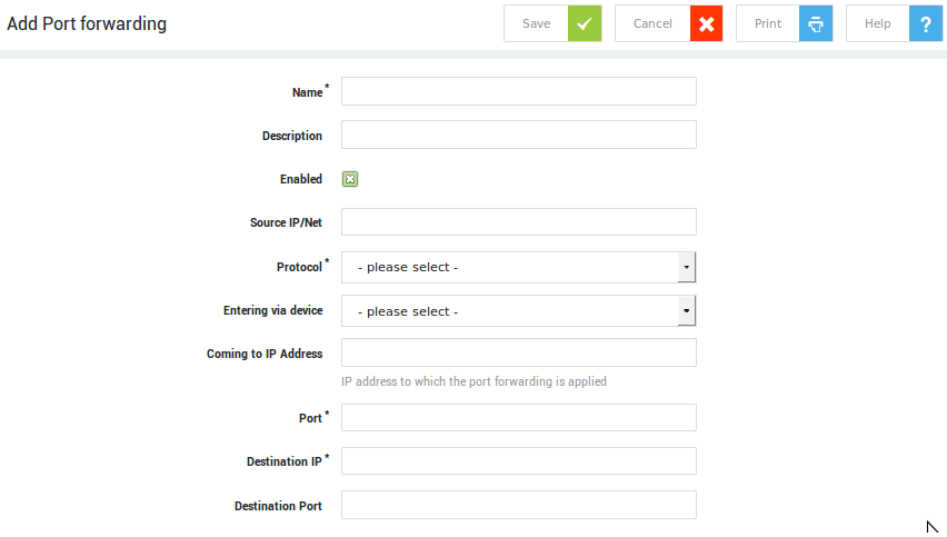
| Field | Description |
|---|---|
Name |
Enter an identifier for the rule, using only lower cases without spaces, starting with an alphabetic character, followed by any number of alphanumeric characters and/or the special characters: back slash |
Description |
Describe the purpose of the port forwarding rule (optional field). |
Enabled |
Check to enable this rule. |
Source |
Restrict port forwarding to the specified source; only traffic originating from this source will be forwarded. If this field is left empty, traffic will be forwarded for any source.
Valid values are:
If a subdomain is resolved by the AXS Guard appliance, its IP address will also be added to the rule. E.g. axsguard.com will match:
|
Source Lists |
Restrict port forwarding to specified geographic sources. Traffic originating from other geographic locations will be discarded. |
Protocol |
Select the appropriate protocol from the drop-down list. The following protocols are supported: TCP, UDP, GRE and ESP. |
Entering via Device |
The network device or network zone that receives the traffic to be forwarded, i.e. the receiving end of the connection. |
Coming to IP address |
The IP address that receives the traffic to be forwarded. |
Port |
The port number or range on the receiving end. Use the x:x format to specify a port range, e.g. |
Destination IP |
The IP address of the host to which traffic must be forwarded. Only one IP may be specified. |
Destination Port |
Forwards traffic to the specified port. This is optional and only relevant for UDP or TCP traffic. |
Log when traffic is accepted by the firewall |
If enabled matching traffic will be recorded in the firewall logs. |
Destination Network Address Translation
Able recommends the use of Port Forwarding rather than DNAT, as it provides control over the specific ports to be forwarded. Forwarding all ports constitutes a serious security risk.
How DNAT Works
Destination Network Address Translation (DNAT) is a special case of port forwarding. With DNAT all connections to a specific IP address are forwarded to another IP address. As with SNAT and masquerading, reverse NAT mapping occurs automatically. This NAT type is almost never used, as port forwarding accommodates most possible requirements.
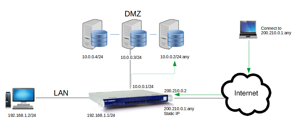
Based on the image above, a connection to 200.210.0.1 on any port, is mapped to 10.0.0.2 on any port (the same port initially used in the connection to 200.210.0.1). The server receives the packet and sends a reply packet with its private IP address, 10.0.0.2. To avoid this packet from being dropped immediately on the Internet as it leaves the LAN, this private IP address is automatically translated to the correct public IP address of the AXS Guard i.e. 200.210.0.1; thus De-NAT is automatic with DNAT. The server in the DMZ cannot be contacted when making a connection to the AXS Guard on IP 200.210.0.2.
Creating DNAT Rules
-
Navigate to Network > NAT > SNAT & DNAT.
-
Click on the Add New button.
-
Configure the settings (see the table in the SNAT section).
-
Click on Save to finish.
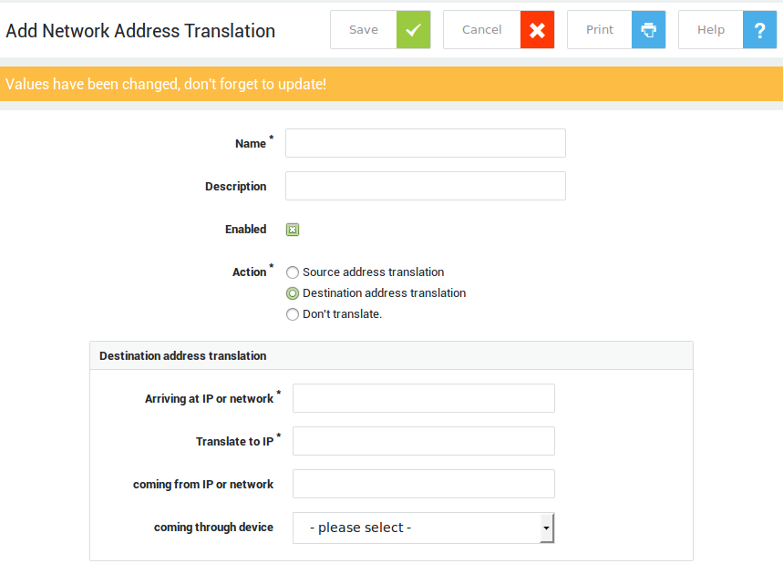
important
- Sometimes you may need a one-to-one NAT of a network range. For example, you have the 192.168.1.0/24 network and you would like to NAT each IP to its equivalent in 192.168.2.0/24 (SNAT) or vice versa (DNAT) when the packet travels through the NAT device. Make sure the subnets do not overlap each other.
- Select
Don't Translatein the Action field if you wish to define exceptions.
Port Redirection
How Port Redirection Works
Port redirection is a NAT type that is used to intercept traffic bound for a certain port and redirects that traffic to another port on the AXS Guard appliance.
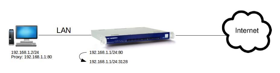
A good example of port redirection is the redirection of http traffic to the proxy (illustrated above). If the browser proxy settings of hosts in the LAN are set to port 80, it is possible to configure a single port redirection rule on the AXS Guard so that all traffic going to port 80 is redirected to port 3128. Port 3128 is the default port number of the AXS Guard Proxy Server. This method is more efficient than modifying the proxy settings on each client.
For information about the use of the AXS Guard proxy server, see the AXS Guard Web Access How To, which is available via the Documentation button.
Pre-defined Port Redirection
important
- Disabling certain predefined port redirection rules may prevent Able from providing remote support.
- Predefined port redirection rules can be disabled, but cannot be removed or altered.
-
Navigate to Network > NAT > Port Redirection.
-
Click on the rule name to view details.
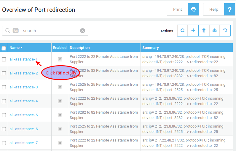
Creating Port Redirection Rules
-
Navigate to Network > NAT > Port Redirection.
-
Click on the Add New button.
-
Configure the settings as explained in the table below.
-
Click on Save to finish.
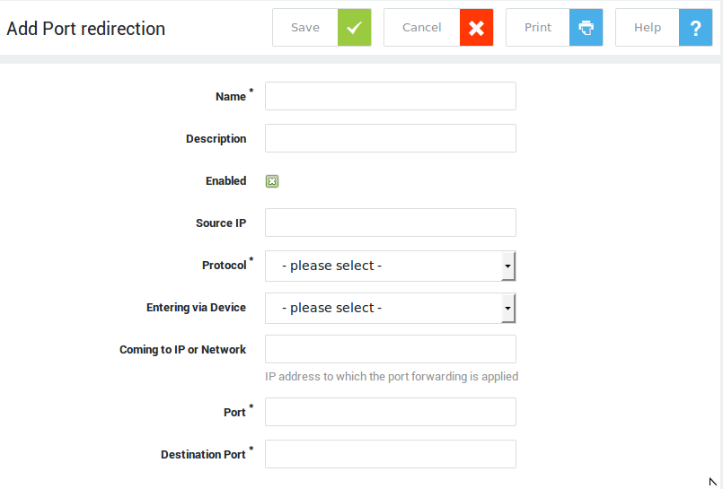
| Field | Description |
|---|---|
Name |
Enter an identifier for the rule, using only lower cases without spaces, starting with an alphabetic character, followed by any number of alphanumeric characters and/or the special characters: back slash |
Description |
Describe the purpose of the rule (optional field). |
Enabled |
Check to enable the rule. |
Source IP/Net |
Restrict redirection to the specified source IP address or subnet. Use the CIDR notation to specify a subnet. If none is specified, traffic coming from any source IP will be redirected. |
Exclude Source IP or Network |
Exclude one or more IP addresses or network ranges from the provided source IP address or network. |
Protocol |
The protocol to be matched. |
Entering via Device |
The network device or zone on the receiving end of the connection. |
Only redirect traffic coming to AXS Guard |
Limit redirection to traffic specifically intended for the AXS Guard device. |
Original Destination IP or Network |
Enter the original destination IP address or range before the redirect. If left blank, the rule applies to all destination IPs. |
Exclude Destination IP or Network |
Exclude one or more IP addresses or network ranges from the provided destination IP address or network. |
Port |
Traffic coming to this port will be redirected to the specified destination port. |
Destination Port |
The port to which traffic must be redirected. |
Ordering NAT Rules
About
The order of Network Address Translation (NAT) rules is critical to correctly process network traffic. AXS Guard evaluates NAT rules sequentially, from top to bottom, applying the first rule that matches. If traffic matches a rule, no further rules will be considered for that specific traffic.
This first match wins principle makes it essential to place specific rules before general rules. By prioritizing specific rules, you guarantee that unique traffic patterns receive their intended translation, while general traffic can then fall through to the broader rules that apply to everything else.
Drag & Drop
- Log in to your AXS Guard appliance.
- Navigate to Network > NAT > Port Forwarding / Port Redirection / Masquerading / SNAT & DNAT.
-
Drag and drop the NAT rules until you reach the desired order.
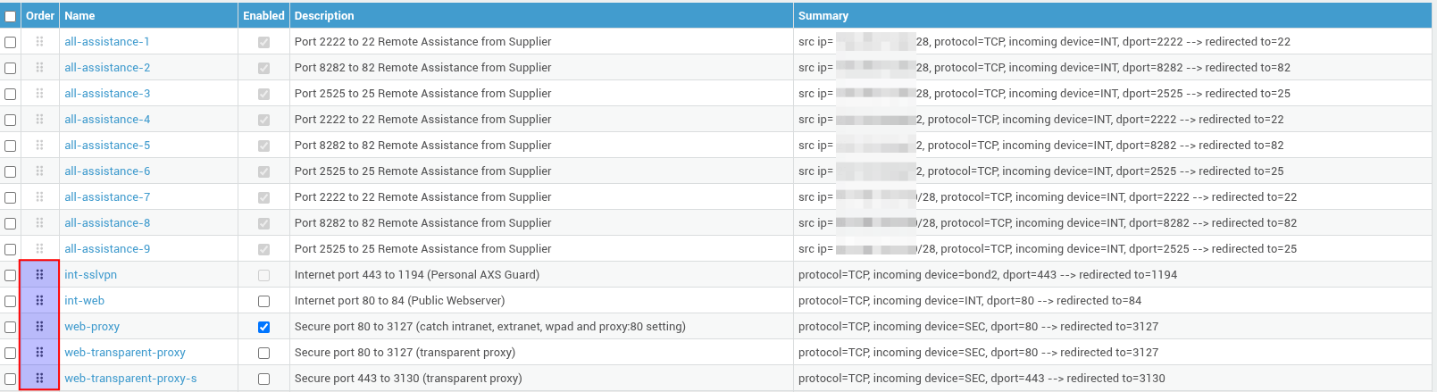
NAT Helpers
What are NAT Helpers?
An important property of the AXS Guard firewall is the use of connection tracking. Connection tracking is the ability to keep records of connection information in tables.
This connection information consists of source and destination IP addresses, port number pairs (also known as socket pairs), protocol types, connection states, timeouts, etc. NAT helpers automatically add the necessary connection information to the connection tables for protocols that require it and ensure that associated connections are properly NATed.
The protocols listed below all use associated connections (control channels) for which NAT helpers can be enabled.
Enabling NAT Helpers
-
Navigate to Network > NAT > NAT Helpers.
-
Enable the NAT helpers that are required in your network (see the table below).
-
Click on Update to finish.
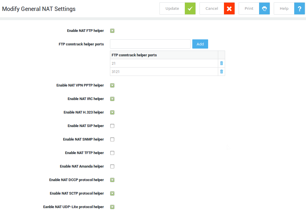
| NAT Helper | Description |
|---|---|
FTP conntrack Helper Ports |
Tracks so-called active FTP connections (ports 21 and 20). |
VPN PPTP Helper |
Tracks TCP port 1723 and the associated GRE tunnel. |
IRC Helper |
Tracks IRC connections on TCP port 6667. |
H.323 Helper |
NAT helper for the H.323 protocol (VoIP). It supports RAS, Fast Start, H.245 Tunnelling, Call Forwarding, RTP/RTCP and T.120 based data and applications including audio, video, chat, whiteboard, file transfer, etc. |
SIP Helper |
NAT helper for the SIP protocol (VoIP). |
SNMP Helper |
NAT helper for the SNMP protocol. This is the ‘basic’ form of SNMP-ALG, as defined per RFC 2962. It modifies IP addresses inside SNMP payloads to match IP-layer NAT mapping. |
TFTP Helper |
NAT helper for the TFTP protocol, which tracks TFTP connections on UDP port 69. |
Amanda Helper |
NAT helper for the Amanda backup tool protocol. |
Network Status Information
Internet Status
Navigate to Network > Status > Internet to view the network status of your Internet connections.
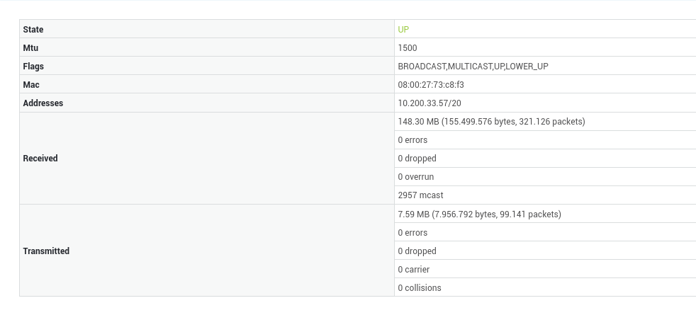
Devices
Navigate to Network > Status > Devices to view network interface controller parameters and statistics. You can make an Ethernet port's LED flash to help quickly identify a specific port, especially when the manual or a printed label is not readily available. Click on blink LED.
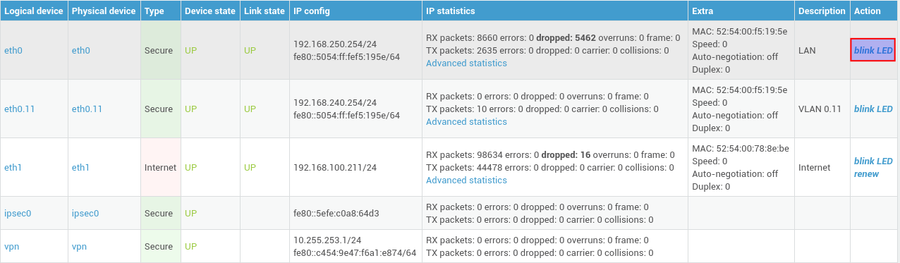
Used Ports
Navigate to Network > Status > Ports for an overview of used ports per service. Ports used in port redirection rules are also listed.
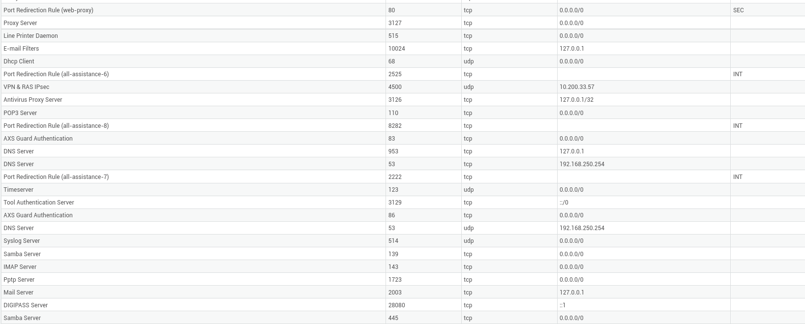
Route Table
See the routing section.
NAT
Navigate to Network > Status > NAT for an overview of NAT rules configured on your system.
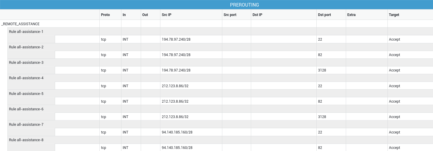
Dynamic IP Ranges
Navigate to Network > Status > Dynamic IP Ranges for an overview of reserved IP ranges.

System Time and NTP
What is NTP?
NTP (Network Time Protocol) is a protocol designed to synchronize the clocks of hosts over a network. The AXS Guard appliance can be used as a time server in your LAN. The AXS Guard’s internal time server is enabled by default and cannot be disabled. Clients in your network need to be configured accordingly to make use of this service. See the documentation of your Operating System for instructions.
A correct system time is critical for time-sensitive processes, such as 2FA and Kerberos authentication.
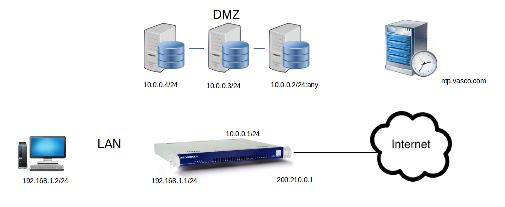
Synchronizing with a Time Server
-
Navigate to Network > General.
-
Enter the FQDN or IP address of an NTP server.
ntp.axsguard.comis the factory default server and is also recommended for security reasons. -
Click on Update.
Important
Using unknown NTP sources on the Internet is dangerous, as they can deliver invalid timestamps or their UDP packets could be spoofed on their way to your clients and devices.
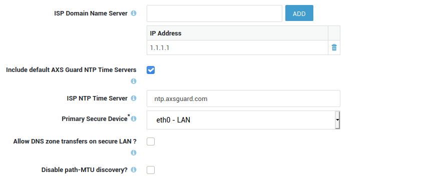
Field |
Description |
|---|---|
ISP Domain Name Server |
The IP address(es) of your ISP’s DNS servers. |
Include default AXS Guard NTP Time Servers |
Many AXS Guard appliance security features such as log generation, backup & restore, certificate validation and two-factor authentication rely on accurate time. With an imprecise time, your connected devices may run into different kinds of errors and you also may encounter various troubleshooting burdens. AXS Guard NTP servers provide redundancy, which means clients and other devices connected to your network will always be able to get the correct time. |
ISP NTP Time Server |
The IP address or FQDN of a time server. |
Primary Secure Device |
Do not change this parameter unless absolutely necessary.
|
Allow DNS zone transfers on secure LAN? |
Check this option to allow DNS zone transfers from the appliance to a secondary DNS server in your LAN. Zone transfers allow DNS servers to synchronize their repositories.
|
Disable path-MTU discovery? |
Check to disable path-MTU discovery for all connections on the appliance, which implicitly enables IP fragmentation for all of them. |
Checking the System Time
The system time of the AXS Guard appliance is permanently displayed in the top pane of the administrator tool.

System Status
Overview
The System Status menu provides general information about the AXS Guard system and specific information about the system’s health, users, services, hardware and the system kernel.
Dashboard
The AXS Guard system dashboard represents key performance indicators and metrics. Click on Dashboard in the top pane or navigate to System > Status > Dashboard to access it.
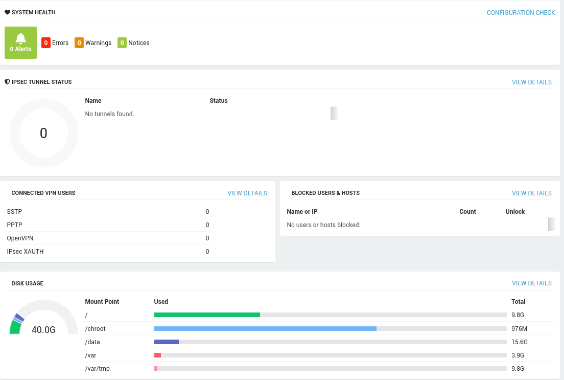
System Info
Navigate to System > Status > System Info to view:
-
the license information
-
the Able contract type
-
Version and Revision numbers
-
Host and Configuration Keys
-
information about the model (Type), Able DIGIPASS and AXS Guard hardware
-
available software features.
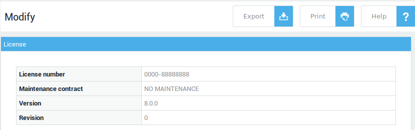
Process Info
Navigate to System > Status > Processes to view detailed process
information, i.e. UNIX-style information about the active processes on
your appliance. You can also request process information using the ps
and top commands via the AXS Guard console. See the CLI How To for more
information.
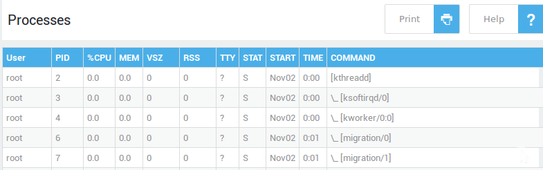
Health Status
The system health screen provides information about:
-
the system’s up time
-
the general health status (OK or Not OK)
-
health status messages.
Accessing the System Health Status
-
Click on the Dashboard button or
-
Navigate to System > Status > Health
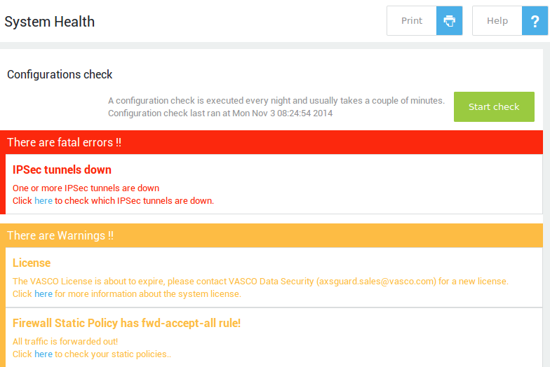
Health Status Message Classification
Health status messages are either run time messages or messages generated after routine self-checks. Health messages are classified according to their severity.
| Type | Description |
|---|---|
Fatal Error |
Critical errors that prevents the correct operation of the appliance or one of its services, e.g. the failure of a network device. |
Error |
Errors do not necessarily prevent the correct operation of the appliance, but need immediate attention as they could affect future operations if left unattended, e.g. a failure of antivirus updates. |
Warning |
Warnings notify system administrators of configuration errors, e.g. when the default sysadmin password has not been changed, which is insecure. |
Notices |
Information about running processes, e.g. when the antivirus engine is being updated. |
Runtime Messages
Run time health messages either offer a link to the configuration page where action needs to be taken or offer information about a configuration problem and/or the action which is required to resolve it.
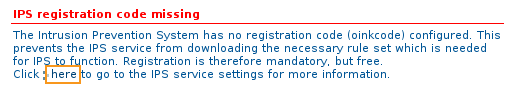
Configuration Warnings
AXS Guard self-checks occur automatically every night and take a couple of minutes to complete. Configuration warnings are generated after the self-checks and are refreshed every 24 hours after every self-check. This means that a configuration warning remains visible until the next self-check. The messages either offer links to interactively resolve problems or explain configuration problems and/or actions needed to resolve them.
-
Navigate to System > Status > Health
-
Click on the Start Configuration Check button (shown below). Note that the configuration check takes a few minutes to complete.
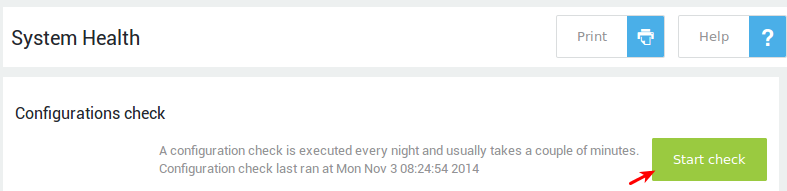
For information on feature-specific health messages and problems, refer to the relevant AXS Guard How To guides, available via the Documentation button.
Services Status
The Services screen displays the status of the AXS Guard services. A stopped service can be (re)started via this screen.
Navigate to System > Status > Services. The fields are explained in the table below.
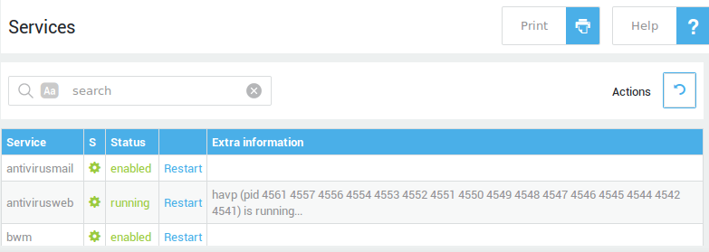
Field |
Description |
|---|---|
Service |
The name of the service. |
S |
|
Status |
Indicates whether the service is stopped, enabled or disabled. |
Action |
Click to restart the service. |
Extra Information |
Provides extra information about the service, i.e. the process ID (PID). |
Hard Drive, UPS and Kernel Status
Other status screens provide information about the AXS Guard’s
-
hard drive(s), e.g. partition information, remaining disk space, etc.
-
connected UPS (if any). Only APC UPS appliances are supported.
-
running Kernel modules and the amount of system memory used by each module.
Go to:
-
System > Status > Hard-Disk for information about the AXS Guard Hard Drive(s).
-
System > Status > UPS for information about connected UPS, if any.
-
System > Status > Kernel Modules for information about loaded Kernel Modules.
High System Load Warning Messages
The AXS Guard appliance will automatically send an e-mail to system administrators if it detects a persistent high system load during 5 consecutive days.
The e-mail notification is sent to the e-mail address(es) entered under System > General.
A high system load average can be an indication of a single process monopolizing a lot of CPU time. A hardware upgrade may be required in that case. Contact the Able sales department for additional information about upgrading your hardware.
System Reports
Threat Reports
The reporting feature allows system administrators to better monitor various types of network and system activity. The aim is threat detection and protection in the context of the General Data Protection Regulation (GDPR). Administrators will be able to generate various types of reports covering a given period, for example:
Authentication and Authorization Report
The authentication and authorization report is an easy way to detect suspicious login activity. If such activity is detected, administrators can intervene immediately by blocking the IP address associated with this activity.
Malware Detection
Malicious software in its various forms remains one of the key threat vectors for today’s organizations. The malware report provides a quick overview of malicious IP addresses, viruses, malware and suspicious DNS queries that have been blocked by AXS Guard.
Resource Access Report
These reports identify various system and application resource access patterns and can be used for both activity audit, trending and incident detection.
Tracking resource access can be used to reveal insider abuse and even fraud. They are valuable during incident response for determining which resources the attacker has accessed and possibly corrupted or modified. In addition, resource access can be used for purposes outside of security, such as capacity planning and other purposes.
Change Reports
These reports highlight changes made to the system configuration and can be used to audit administrator activity. For example, updating user accounts, changes to the firewall, etc.
Unauthorized changes to information systems can lead to costly crashes and the loss of data and may indicate security incidents. On top of this, attackers will often modify your systems in order to enable their access in the future. Being diligent with tracking changes will also improve your overall IT operation.
Viewing Threat Reports
-
Go to Reports > Threats.
-
Select the desired report type, e.g. authentication and authorization.
-
Select the desire subtype, e.g. Login Activity.
-
Select the desired period.
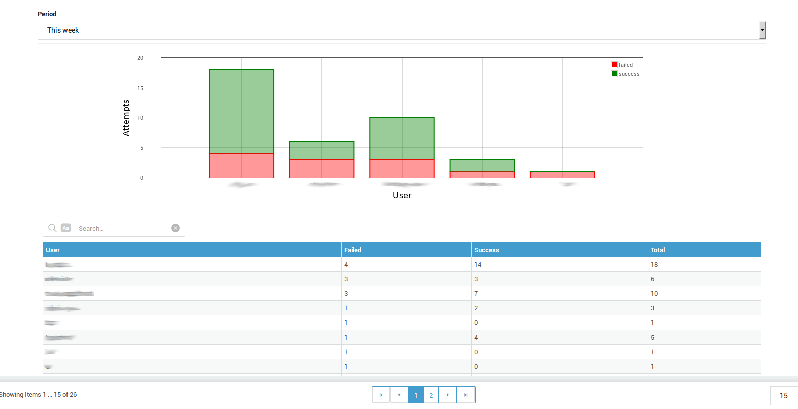
Info
Reports may also contain usernames linked to internal system processes, e.g. cyrus. This is expected behavior. System processes should never indicate a login failure. If a login failure is, however, detected, administrators should check the full event logs.
Mail Usage Reports
-
Navigate to Reports > Mail Usage.
-
Select the desired period.
-
Click on the appropriate more link.
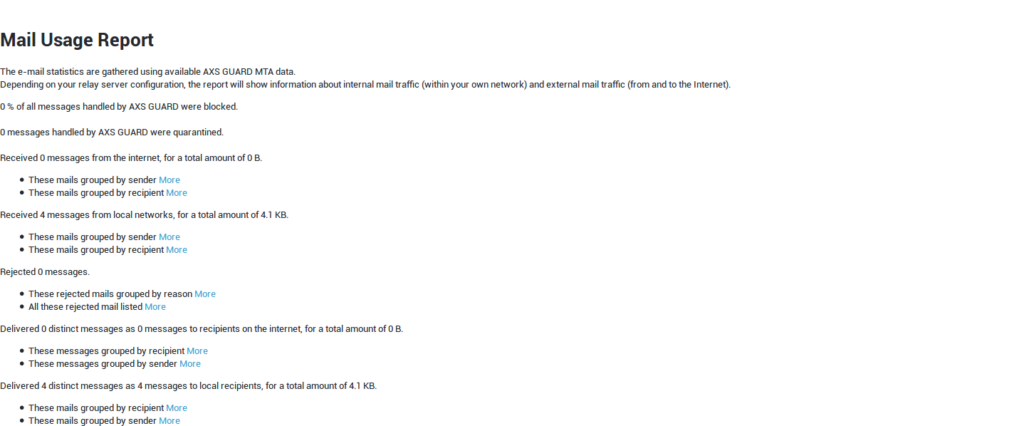
Info
Click on an area in the pie chart for additional details.
Web Access Usage Reports
-
Go to Reports > Web Access Usage.
-
Select the period for which a report must be generated.
-
Click on the appropriate more link.

Configuring your own Reports
Automated security audit reports bring relevant and useful system information to administrators via e-mail, so they don’t have to seek out the information for themselves. This allows them to better monitor various types of network activity and identify potential threats in a GDPR context.
A default export configuration is available for convenience. This
configuration cannot be modified, only enabled. If you wish to base your
own export configuration(s) on the system default configuration, simply
click on its name in the overview and use the edit as new button.
Reports are mailed to the specified recipient, based on the selected frequency. Note that access to the reporting feature is restricted to reporting users or users with higher access privileges. You can test report configurations by clicking on the Send Test E-mail button.
-
Go to Reports > Configuration.
-
Click on "add new".
-
Configure your system report settings as explained in the table below, then save your configuration.
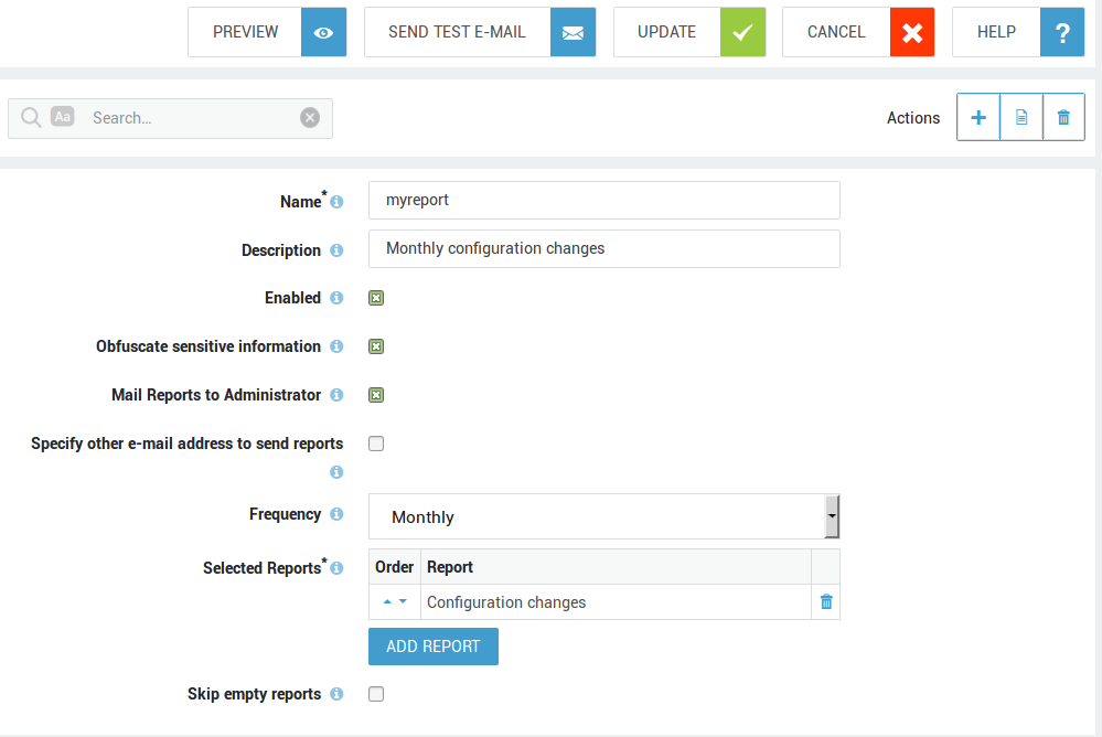
Info
The report configuration page is also accessible via the AXS Guard dashboard.

| Options | Description |
|---|---|
Name |
Enter a name for your export profile, using lower cases without spaces, starting with an alphabetic character, followed by any number of alphanumeric characters and/or the special characters: back slash (\), hyphen (-), underscore (_), full stop(.) or the "at" sign (@). |
Description |
Use a sensible description to facilitate the configuration and management of your export profiles. The description will also appear in the export profile overview. |
Enabled |
Check to enable the export profile. If enabled, selected reports will be mailed to the specified e-mail addresses. |
Obfuscate sensitive information |
If checked, sensitive data in reports will be masked. The aim is to secure confidential information that may directly or indirectly reveal an individual’s identity. |
Defang URLs and e-mail addresses |
If enabled, all URLs will be modified to make them non-functional while remaining readable. This protects against accidental clicks on potentially harmful links and ensures they do not trigger spam filters. |
Mail Reports to Administrator |
If checked, the appliance will send the selected reports to the e-mail addresses specified under System ▸ General. |
Specify other e-mail address to send reports |
Select to specify additional e-mail addresses, e.g. an external e-mail address. |
E-mail Addresses to send reports to |
This field only appears if you selected the previous option. Enter the desired e-mail address and press the add button. Repeat the steps to add other addresses. |
Selected Reports |
Select the reports to be included in the e-mail. Reports will appear in the specified order. The order can be changed by clicking on the arrows in the order column. Press the preview button to view your current configuration and adjust the order if necessary. |
Skip empty reports |
Select to exclude reports which don’t contain any data. An e-mail will not be sent if no data is present in any of the selected reports. |
Frequency |
Automated e-mails will be sent as scheduled. Monthly is the factory default configuration, which means selected reports will be sent on the 1st of each month. |
Statistics
Overview
System statistics like CPU usage, memory usage, and disk space are crucial for understanding a system's health.
They help identify bottlenecks, such as high CPU usage slowing down AXS Guard processes, or low memory causing crashes. Monitoring network devices, connections, and bandwidth helps diagnose internet slowdowns and potential security risks.
Application control goes beyond just visibility. It empowers you to prioritize tasks by identifying which programs are consuming resources. Additionally, it allows you to block unnecessary applications, further optimizing system performance and potentially mitigating security risks.
Overall, system statistics provide valuable insights to optimize performance, troubleshoot problems, and maintain system stability.
Accessing Statistics
- Log in to your AXS Guard appliance.
- Navigate to Statistics.
-
Select the appropriate item to view its statistics.

Use the sliders, zoom tools, intervals and other interactive elements to adjust your view of the content.
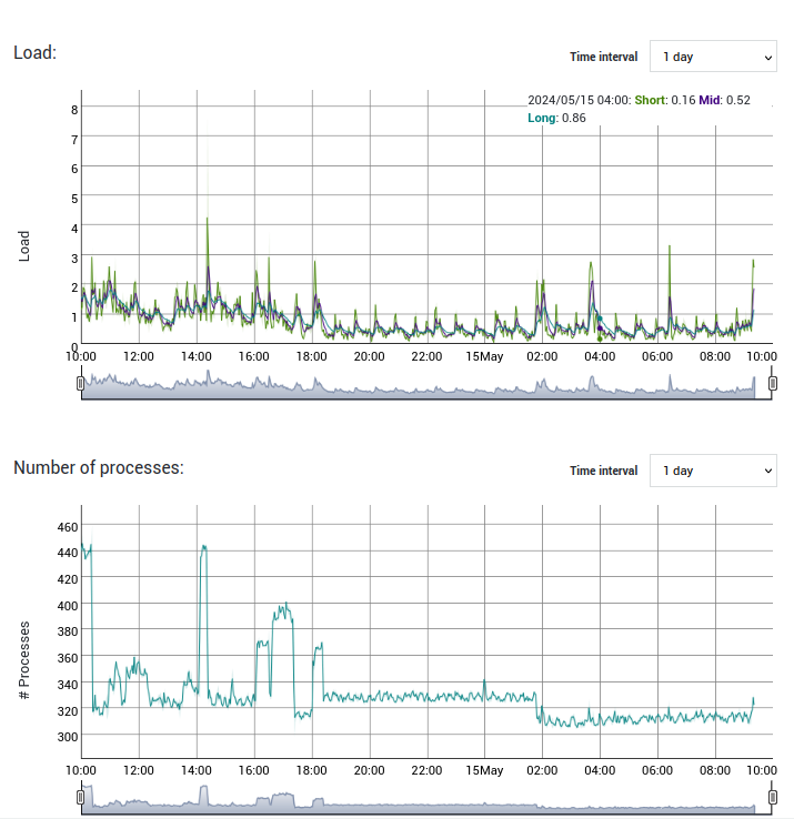
Monitoring Specific Process Groups
By monitoring critical process groups, you can proactively identify and address potential issues, ensuring the smooth operation and security of your system.
- Navigate to Statistics.
-
Select processes, then the appropriate process group to view the associated statistics.
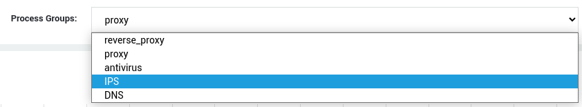
| Metric | Description |
|---|---|
| Process Count | Monitor for unexpected fluctuations or spikes that might indicate overloading or service disruptions. |
| CPU Usage | High CPU usage can lead to slowdowns. Identify processes within the group that are consuming excessive resources. |
| Memory Usage | Excessive memory usage can impact overall system performance. Track memory allocation for each process. |
| Page Faults | Monitor the rate of page faults to identify potential memory access issues or inefficient memory usage. |
| File Descriptors | Track the number of open file descriptors to identify potential resource leaks or bottlenecks. |
System Logs
Overview
This section explains how to access and use the system logs of the AXS Guard appliance. Logs are displayed in chronological order by default and are labeled using the YYYY-MM-DD date format. The log size is shown in kilobytes (KB).
Accessing Log Files
-
Go to System > Logs.
-
Select the desired type, for example
Admin Tool. -
Click on the date to view the log entries.
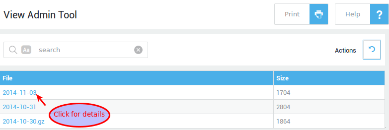
Info
Use search filters to look for a particular log entry.
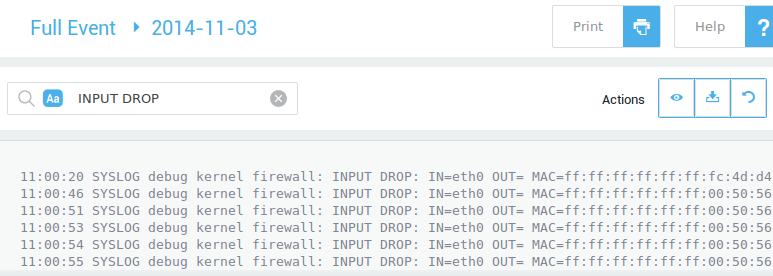
Log Types
| Type | Description |
|---|---|
Update History Log |
Logs of all software update events. |
Test Update History Log |
Logs of all version tests. |
Administrator Tool Log |
Records all actions performed by system administrators, along with the reasons for those actions (change management). |
Boot Log |
Indicate when the system was booted up and shut down. |
Network Security Logs |
A compilation of logs related to traffic blocked by the firewall, the IPS, SecureDNS, GeoIP filtering and the application control system. |
Full Event Log |
A compilation of all the logs which are available on the appliance. |
Other Log |
A smaller version of the full event Log, with feature-related entries filtered out. |
Remote Syslog |
Logs sent to the appliance by another log server in its network, configured under System > Syslog. |
Remote Syslog Management
Overview
Managing log files is a vital part of network administration. The syslog management utility offers you the ability to log system activities locally and remotely. This capability can be essential if you need to archive log files for a long period of time or simply want log files to be available on other systems in your network.
The syslog management utility allows you to centralize AXS Guard log files on a single server or to distribute them over several servers per facility or service, e.g. to store all e-mail log files on server A and firewall logs on server B.
Supported Delivery Types
-
Local delivery: refers to logs that are generated by and stored on the AXS Guard appliance.
-
Network delivery: refers to logs that are forwarded by a dedicated log server to and stored on the AXS Guard appliance.
-
Relay delivery: refers to logs that have been delivered to the AXS Guard appliance (see network delivery). Once the logs are received, the AXS Guard appliance relays them to another log server as specified in the configuration.
-
Mail delivery: the AXS Guard appliance sends logs by e-mail to the specified addresses.
Local Delivery
By local delivery, we mean the local logging system of the AXS Guard. This option is enabled by default. We strongly recommend not to disable this option, unless there is insufficient disk space on your appliance or if you are using it as a log relay server.
Network Delivery
The AXS Guard’s log service enabled by default. This allows services in your secure network to forward log messages to the appliance. To use this functionality, you must configure the service(s) in your secure network to forward their logs to the AXS Guard, which listens on UDP Port 514.
For information about the appliance’s firewall configuration, see the AXS Guard Firewall How To, which is accessible by clicking on the permanently available Documentation button in the Administrator Tool.
Personal AXS Guard clients forward their log messages to the AXS Guard VPN server as soon as the VPN Tunnel is up.
Important
Never expose UDP port 514 on the Internet side of your appliance. Only allow access from trusted networks, i.e. hosts in your LAN or connected via a VPN.
Relay Delivery
The AXS Guard’s log service has the ability to relay its local logs and logs received via the network to another log server in your network. Relay delivery is disabled by default and must be enabled before you can configure log relaying for any facility or service.
A default log relay is available for ease of configuration and allows you to relay all logs to (a) specific server(s). Enter the IP(s) or the hostname(s) of the target log servers and create the necessary relaying entries for each service or facility.
E-mail Delivery
If enabled, the appliance will forward log files the specified e-mail address(es) at the specified intervals.
Facilities and Services
A Facility is the proprietary log of a service running on the AXS Guard, e.g. OpenVPN produces its own log files, IPsec produces its own log files, etc.
A Service may contain one or more Facilities, e.g. the VPN Service contains the following Facilities: IPsec, PPP, OpenVPN, SSL VPN and the Personal AXS Guard. The Monitoring Service only contains one Facility, namely IPS.
Relaying can be configured per Facility or per Service. Local logging can only be configured per Facility.
Supported Log Formats
The log type mainly influences the formatting of relayed log messages, i.e. logs that are relayed by the AXS Guard to a log server. Details about the various formats are outside the scope of this manual. For detailed information about the supported formats, see the corresponding RFC of the list below via http://www.ietf.org/rfc.html.
The following log types are supported:
-
RFC 3164: This is the system default type and is the most human-readable format.
-
RFC 3339: This format contains the most details (e.g. timestaps)
-
Unix: Used by older servers and less detailed than RFC 3164 and 3339.
-
CEF (ArcSight Common Event Format): Facilitates the integration of logs from various vendors.
If you are using your appliance as a log server and relay simultaneously, and the source server generates Unix type logs, the AXS Guard will insert extra log headers before forwarding the logs to the target log server.
Remote Syslog Configuration
General Settings
In this section we explain how to enable the delivery type.
-
Log on to the AXS Guard.
-
Navigate to System > SysLog > Delivery Options.
-
Check to enable / Uncheck to disable the desired delivery.
-
Click on Update
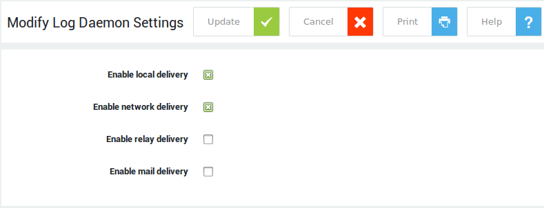
Important
Relay Delivery has to be enabled if you wish to relay logs for any service or facility.
| Option | Description |
|---|---|
Enable Local Delivery |
The logs that are generated locally on the appliance. This option is enabled by default. Do not to disable, unless there is insufficient disk space on your appliance or if you are using the appliance as a log relay. |
Enable Network Delivery |
Allows log servers in your secure network to forward log messages to the syslog server of the appliance, which listens on UDP Port 514. |
Enable Relay Delivery |
The appliance can relay logs to another log server in your network. Relay delivery is disabled by default and must be enabled before you can configure log relaying for any facility or service. |
Enable Mail Delivery |
If enabled, the appliance will be able to send log files by e-mail to the specified address(es) at the specified intervals. |
Local Delivery
In this section we explain how to configure Local Logging. Only three parameters need to be configured at the Facility level. The parameters are explained in the table below.
-
Enable Local Logging.
-
Navigate to System > SysLog > Facilities.
-
Select the desired Facility, e.g. OpenVPN.
-
Modify the settings as explained in the table below.
-
Click on Update.
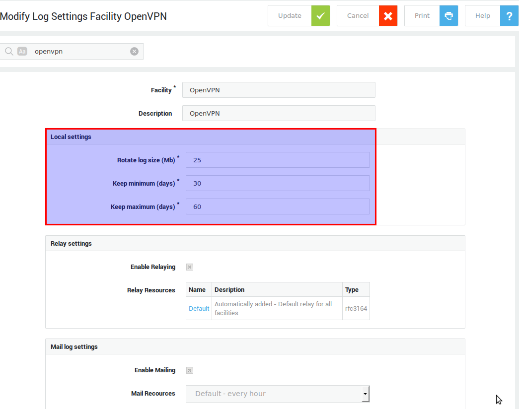
| Option | Description |
|---|---|
Rotate Log Size |
Log rotation occurs when a log file reaches the specified size, i.e. a new log file is created. |
Keep Minimum |
The minimum number of days that the log files are to be kept on the system. Enough disk space must be available on the appliance for the specified minimum to be allowed (Disk usage must remain under 90% of the total available capacity). |
Keep Maximum |
The maximum number of days that the log files are to be kept on the system. Disk space restrictions also apply. |
Network Delivery
-
Enable the Network Logging option.
-
Click on Update.
The configuration for local storage is done via the Remote Syslog Facility. To change the default settings of the Remote Syslog Facility:
-
Navigate to System > Syslog > Facilities.
-
Select Remote Syslog.
-
Change the appropriate settings.
-
Click on Update.
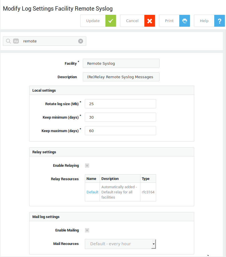
Info
- The log files which are sent to the AXS Guard can be viewed by navigating to VPN&RAS > Logs > Personal AXS Guard > Clients.
- Network Logs can be relayed too.
Relay Delivery
Overview
In this section we explain how to configure Relay Logging. This consists of the following steps:
-
Enable Relay logging as explained in section.
-
Configure the Log Relay Resources: a server or group of servers to which logs are relayed in the supported formats.
-
Enable the Relay Resource(s) at the Service or Facility level.
Log Resource Configuration
-
Enable the Log Relaying option.
-
Navigate to System > Syslog > Relays .
-
Click on Add New.
-
Enter the settings as explained in the table below.
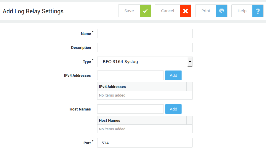
Option |
Description |
|---|---|
Name |
A label for the network resource. |
Description |
An optional description for the resource. |
Type |
For detailed information, see the corresponding RFC on http://www.ietf.org/rfc.html. |
Host Names / IPv4 Addresses |
The FQDN, e.g. |
Port |
The port on which the network resource listens. The system default is UDP port 514. |
Info
Use the existing Default Relay definition when all logging needs to be forwarded to a specific relay server. This is much easier, since you only need to add the host name or IP address to this Definition. This Relay is assigned and enabled by default for all the Facilities (i.e. there is no need to follow the steps explained in the next subsections).
Using a Relay Resource
You can use Relay Resources at the Facility level or at the Service Level.
-
Navigate to System > Syslog > Facilities.
-
Select the appropriate Facility from the list.
-
Enable Relaying.
-
Add the appropriate log resource by clicking on the Add Relay Resources button.
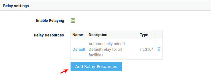
Field |
Description |
|---|---|
Enable Relaying |
Check to enable log relaying. |
Relay Resources |
Select the desired relay resource(s) as configured under System > Syslog > Relays. |
Using a Relay Resource at the Service Level:
-
Navigate to System > SysLog > Services.
-
Select the desired Service.
-
Enable Relaying (select Yes).
-
Add the appropriate log resource by clicking on the Add Relay Resources button.
-
Configure the appropriate Relay Resource(s) by clicking on the Change Relays Button.
-
Click on Update.
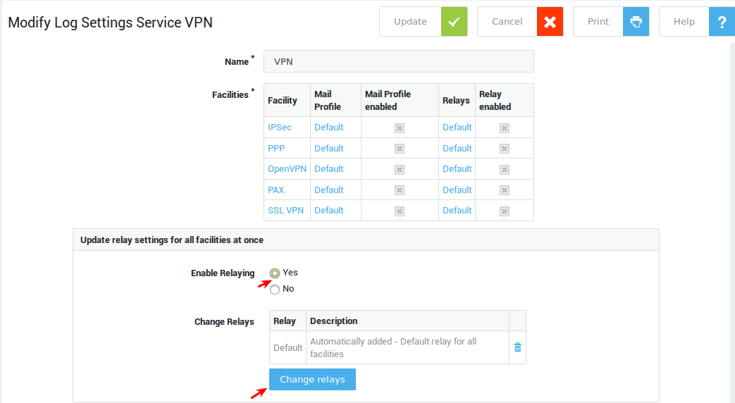
Option |
Description |
|---|---|
Enable Relaying |
|
Change Relays |
Click on this button to change or select the relay. The relay must exist under System > Syslog > Relays. |
Mail Delivery
Overview
Configuring a mail resource consists of the following steps:
-
Enable mail delivery under System > Syslog > General.
-
Configure the mail resource by adding the desired recipients.
-
Assign the mail resource to the appropriate service or facility.
Log Resource Configuration
-
Go to System > Syslog > Mail
-
Click on add new.
-
Configure the settings as explained in the table below.
-
Save your configuration.
-
Assign the policy to a facility or a service.
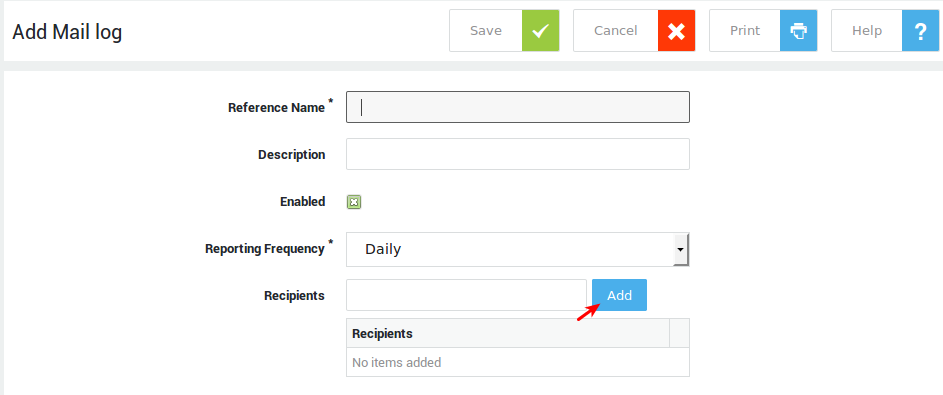
Field |
Description |
|---|---|
Reference Name |
A name for the mail resource. |
Description |
A description for the mail resource (optional field). |
Enabled |
Check to enable the mail resource. |
Reporting Frequency |
Select the desired frequency from the drop-down list. |
Recipients |
Logs will be sent to the specified e-mail address(es). |
Using a Mail Resource
You can use Mail Resources at the Facility level or at the Service Level.
-
Navigate to System > Syslog > Facilities.
-
Select the appropriate Facility from the list.
-
Enable Mailing under Mail log settings.
-
Select the mail resource and save your settings.
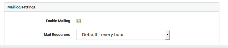
Field |
Description |
|---|---|
Enable Mailing |
Check to enable mail delivery. |
Mail Resources |
Select the desired mail resource as configured under System > Syslog > Mail. |
Using a Mail Resource at the Service level:
-
Navigate to System > Syslog > Services.
-
Select the appropriate Service from the list.
-
Enable Mailing under Mail log settings.
-
Select the mail resource and save your settings.
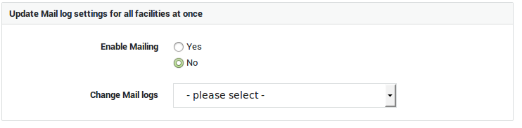
Field |
Description |
|---|---|
Enable Mailing |
|
Mail Resources |
Select the desired mail resource as configured under System > Syslog > Mail. |
Authentication Settings
Overview
AXS Guard can be used as a standalone authentication appliance or as a UTM appliance providing strong authentication and Internet security. It supports the following authentication features:
-
One-factor authentication and two-factor authentication, e.g. DIGIPASS Authentication.
-
Local and back-end authentication: credentials can be checked locally on the AXS Guard or via a back-end server in its network.
-
The AXS Guard can be installed as a RADIUS server, a RADIUS client or a combination of both.
-
The AXS Guard can be synchronized with an LDAP back-end, such as a Microsoft Directory Server.
Important
If you are using the DIGIPASS authentication and management functionalities of the AXS Guard appliance, you must set a Derivation Key before any DIGIPASS tokens can be imported and deployed. For detailed information about authentication, see the AXS Guard Authentication and Directory Services manuals.
Setting the Derivation Key
The derivation key is a string which consists of 16 ASCII characters used to encrypt or decrypt the AXS Guard DIGIPASS database. It provides physical security, in that access to the AXS Guard hard drive(s) alone is not sufficient to read DIGIPASS data. The derivation key must be entered by an AXS Guard user with full administrative privileges or above before any DIGIPASS blob data can be imported. A derivation key can only be changed by a full system administrator or above.
-
Log in to the AXS Guard appliance.
-
Go to Authentication > Able DIGIPASS > General.
-
Enter the Derivation Key in the Derivation Key used for data crypto field.
-
Save your settings.
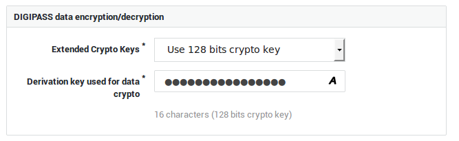
SNMP
About
The Simple Network Management Protocol or SNMP is an application–layer protocol defined in RFC 1157. It is used for exchanging management information between network devices and is a widely accepted network protocol that allows system administrators to manage and monitor network elements.
Most professional–grade network devices come with an SNMP agent, including AXS Guard.
Management Information Base (MIB)
Every SNMP agent maintains an information database which describes the managed device parameters. SNMP managers and browsers, such as snmpwalk or FrameFlow, can use this database to request the agent for specific information and further translate the information as needed for the Network Management System.
The shared database between the SNMP agent and the SNMP manager is called a Management Information Base (MIB).
MIB files are ASCII text files that describe SNMP elements as a list of data objects. They can be considered as a dictionary of the SNMP language. Their fundamental purpose is to translate numerical strings or OIDs into human-readable text.
SNMP on AXS Guard
Implementation
AXS Guard uses the NET-SNMP implementation and also provides custom MIB files for disk monitoring. The MIB files for your SNMP manager can be downloaded from the NET-SNMP website; the custom MIB files must be downloaded via the AXS Guard add-ons page.
Check the documentation of your SNMP manager for information on how to import the MIB files so that you will be able to perform SNMP queries.
SNMP Service
The SNMP service runs by default and cannot be disabled.
To verify the status of the AXS Guard SNMP agent, follow these steps:
- Log in to your AXS Guard appliance.
- Go to System > Status > Services.
- Look for
snmpas shown in the example below.
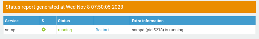
SNMP Traps & Queries
About SNMP Traps
SNMP traps are not supported by AXS Guard; you can only query data sets.
Supported SNMP Versions
| SNMP Version | Supported |
|---|---|
| SNMPv1 | |
| SNMPv2c | |
| SNMPv3 |
Firewall Configuration
The AXS Guard SNMP agent listens on UDP port 161. This port is firewalled by default and must be made accessible before queries can be sent.
-
Log in to your AXS Guard appliance.
-
Go to Firewall > Policies > Static.
-
Add the
sec-snmprule to thestat-secpolicy and update your configuration.
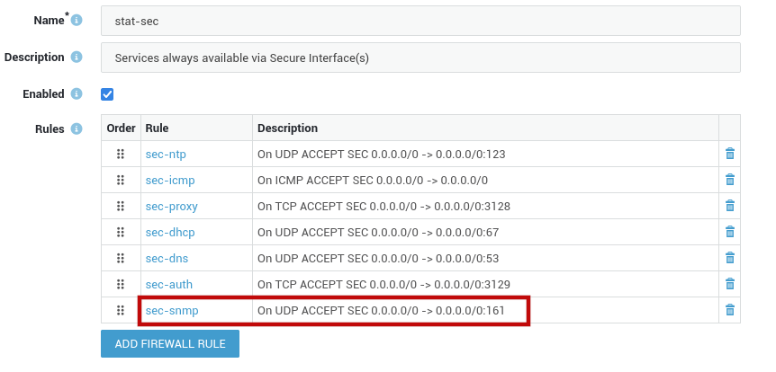
SNMP Community String
The SNMP community string is a basic form of authentication used to control access to SNMP-enabled devices. It is recommended to change the factory default SNMP community string for security reasons.
Go to Network > General to configure the community string for the AXS Guard SNMP server.
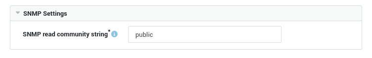
Query Examples
Parameters
| Parameter | Description |
|---|---|
| comm | Go to Network > General to configure the AXS Guard SNMP community string. The system default community string is public. |
| host | IP address of your AXS Guard appliance. |
| key | The information to be queried, e.g. system. |
snmpwalk
snmptable
You can query AXS Guard disk partition information with snmptable, using the MIB files provided via the AXS Guard add-ons page.
- Log in to the AXS Guard appliance.
- Navigate to Add-ons.
- Download the AXS Guard MIB files.
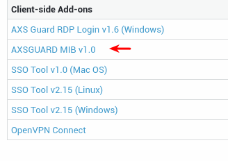
snmptable -CB -v 2c -c public -m all -m mibs/AXSGUARD-MIB.txt 192.168.250.254:161 partitionTable

 filesystem size used available percentage type iNodes iUsed iFree iPercentage mountLoc
      name1 1001  101       101         11 ext3   1001    11   101          11     /lme
      name2 2001  201       201         21 ext3   2001    21   201          21   /lme_2
FrameFlow
FrameFlow is a free SNMP browser for Windows and allows you to scan your devices and see the complete list of SNMP values that they support. With its tree-based display and filtering capabilities, you can quickly find the values you are looking for.
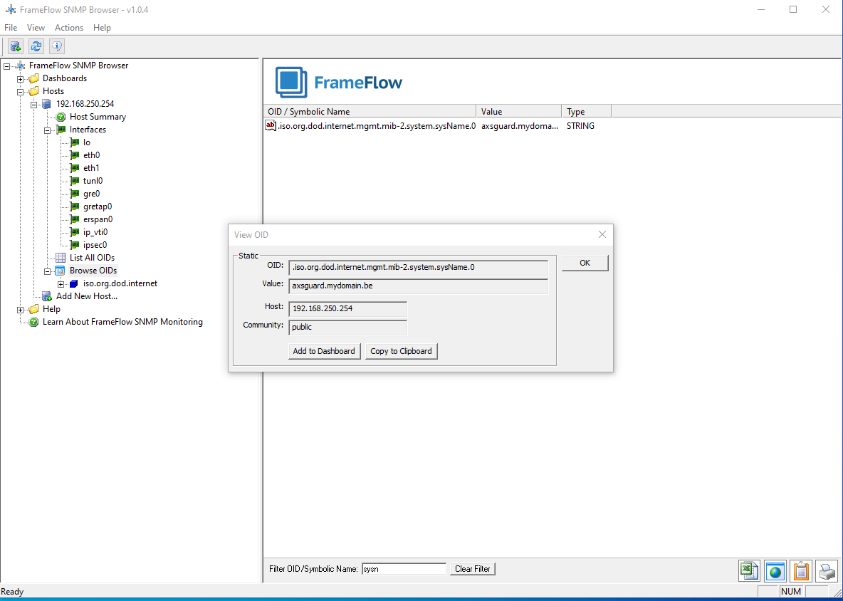
Troubleshooting
I cannot access the AXS Guard administrator tool.
-
Ping the LAN IP address of the AXS Guard. The factory default LAN IP address is
192.168.250.254. If the network is unreachable, check the IP address and subnet of your client. -
If you can ping the LAN IP address of the AXS Guard, check the proxy settings of your Internet browser and adjust them if necessary. Consult the documentation of your Internet browser if necessary.
I cannot log in to the administrator tool with IE or Chrome.
If you log in to the Administrator Tool using Internet Explorer or Chrome on Windows XP SP2, the connection will fail as of AXS Guard version 7.7.0.
As of version 7.7.0, Windows XP SP3 or later versions of the OS are required to log in to the administrator tool, because the appliance will be using the SHA-256 algorithm to sign its certificates. This algorithm is only supported by Windows XP SP3 and later versions of the Windows OS.
Firefox can be used to log in to the administrator tool on Windows XP SP2.
A purchased software option is missing from the AXS Guard menu.
A newly purchased AXS Guard software option must be activated under Feature Activation before it can be accessed for configuration.
I cannot log in to the administrator tool.
Check that the user account is permitted to access the Administrator Tool:
-
Navigate to Users and Groups > Users.
-
Click on the Mailbox / User name.
-
Make sure the user account is enabled.
-
Click on the AXS Guard Administration tab.
-
Check that the correct Tool Access Type has been configured for the user.
As of version 7.7.0, AXS Guard uses the SHA-256 algorithm to sign digital certificates. SHA-256 is only supported by Windows XP SP3 and later versions. Logging in to the web-based administrator tool will no longer be possible with older versions of Windows.
Users cannot change their AXS Guard password.
-
Check that the correct Tool Access Type has been configured for the user.
-
Check that the user is allowed to change his/her password, by navigating to Users and Groups > General. The May users change their passwords? option must be checked.
I corrected the configuration, but still get an error message
Some system health messages are only refreshed after the self-checks which are completed every 24 hours. To test your configuration settings and force the health messages to be refreshed immediately:
-
Navigate to System > Status > Health.
-
Click on the Start Configuration Check button. Please note that the configuration check takes a few minutes to complete. If the configuration has been corrected, the message will no longer be displayed.
tool does not seem to resolve.
-
Check your browser’s proxy settings.
-
Navigate to System > Administrator Tool and check whether the name to go to the Administrator Tool has been changed.
Clients are unable to resolve hostnames.
Try disabling the SecureDNS feature and use the DNS servers of your ISP. If the problem persists, contact the customer service department.
Some DNS name queries are unsuccessful after deploying a Windows-based DNS server.
This issue occurs because of the Extension Mechanisms for DNS (EDNS0) functionality that is supported in Windows Server DNS.
EDNS0 allows larger UDP packet sizes. However, AXS Guard does not allow UDP packets that are larger than 512 bytes by default. See RFC 6891 for additional information about EDNS0.
To resolve this issue, disable the EDNS0 feature on your Windows server. See the official Microsoft documentation for additional information.
How to allow large DNS queries over TCP.
Regular DNS queries (UDP port 53) have a 512 bytes limit and AXS Guard does not allow UDP packets that are larger than 512 bytes by default.
UDP can only be used to exchange small information, whereas TCP must be used to exchange information larger than 512 bytes, e.g. for DNS zone transfers (AXFR) and retransmission.
If a client does not get a response from a DNS server, it must retransmit the DNS query using TCP after 3-5 seconds of interval.
DNS over TCP can be enabled on AXS Guard by adding the sec-dns-tcp rule to the stat-sec firewall policy.
Support
If you encounter a problem
If you encounter a problem with AXS Guard, follow the steps below:
-
Check the troubleshooting section of the feature-specific manual.
-
Check the knowledge base on this site for information about special configurations.
-
If no solution is available in any of the above sources, contact your AXS Guard vendor.
Contact Information
(+32) 15-504-400
support@axsguard.com